Toyota Yaris: G16e-gts (starting) / Engine Switch
Components
COMPONENTS
ILLUSTRATION
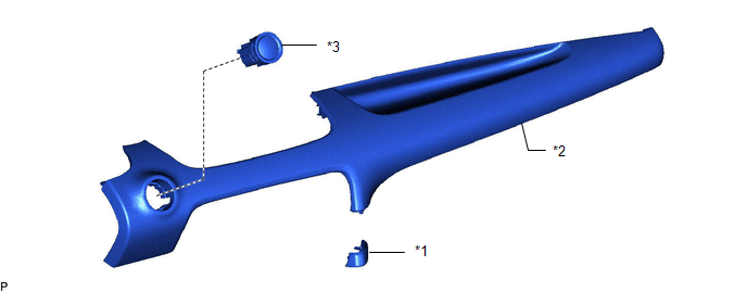
| *1 | CENTER LOWER INSTRUMENT COVER | *2 | LOWER INSTRUMENT PANEL FINISH PANEL |
| *3 | ENGINE SWITCH | - | - |
Removal
REMOVAL
PROCEDURE
1. REMOVE CENTER LOWER INSTRUMENT COVER
Click here

2. REMOVE LOWER INSTRUMENT PANEL FINISH PANEL
Click here

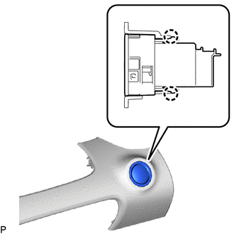
3. REMOVE ENGINE SWITCH
(a) Disconnect the connector.
| (b) Disengage the 2 claws and remove the engine switch from the lower instrument panel finish panel. |
|
Inspection
INSPECTION
PROCEDURE
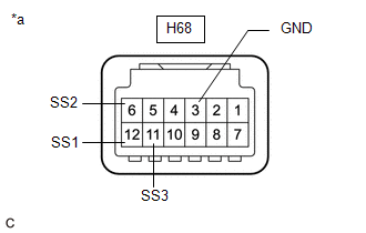
1. INSPECT ENGINE SWITCH
(a) Check the resistance.
| (1) Measure the resistance according to the value(s) in the table below. Standard Resistance:
If the result is not as specified, replace the engine switch. |
|
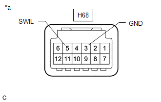
(b) Check the LED illumination.
| (1) Apply battery voltage between the terminals of the engine switch and check the illumination condition of the engine switch indicator light. OK:
HINT:
If the result is not as specified, replace the engine switch. |
|
Installation
INSTALLATION
PROCEDURE
1. INSTALL ENGINE SWITCH
(a) Engage the 2 claws to install the engine switch to the lower instrument panel finish panel.
(b) Connect the connector.
2. INSTALL LOWER INSTRUMENT PANEL FINISH PANEL
Click here

3. INSTALL CENTER LOWER INSTRUMENT COVER
Click here


 Relay
Relay
InspectionINSPECTION PROCEDURE 1. INSPECT ST NO. 1 RELAY (a) Check the resistance. (1) Measure the resistance according to the value(s) in the table below...
Other information:
Toyota Yaris XP210 (2020-2026) Reapir and Service Manual: Installation
INSTALLATION PROCEDURE 1. TEMPORARILY INSTALL PROPELLER SHAFT WITH CENTER BEARING ASSEMBLY (a) Completely remove any oil or the like and clean the contact surfaces of the transfer assembly and propeller shaft with center bearing assembly. (b) Completely remove any oil or the like and clean the contact surfaces of the rear differential carrier assembly and propeller shaft with center bearing assembly...
Toyota Yaris XP210 (2020-2026) Reapir and Service Manual: ECM Power Source Circuit
DESCRIPTION When the ignition switch is turned on (IG), the auxiliary battery voltage is applied to IGSW of the ECM. When the transistor in the MREL circuit operates, current flows from the auxiliary battery to ground through the drive circuit of the EFI-MAIN NO...
Categories
- Manuals Home
- Toyota Yaris Owners Manual
- Toyota Yaris Service Manual
- Brake System Control Module "A" System Voltage System Voltage Low (C137BA2)
- Headlights
- Fuse Panel Description
- New on site
- Most important about car
Liftgate/Trunk Lid
WARNING
Never allow a person to ride in the luggage compartment/trunk
Allowing a person to ride in the luggage compartment/trunk is dangerous. The person in the luggage compartment/trunk could be seriously injured or killed during sudden braking or a collision.
Do not drive with the liftgate/trunk lid open