Toyota Yaris: Power Steering System / Power Steering Motor "A" Supply Voltage Circuit Voltage Below Threshold (C155A16,C155A17,C155B16,C155B17)
DESCRIPTION
If a problem occurs in the system, the power source relay circuit and the motor relay circuit are shut off to stop power assist. The ECU must be replaced when there is a problem with the relays because the relays are built into the ECU.
| DTC No. | Detection Item | DTC Detection Condition | Trouble Area | Warning Indicate | Return-to-normal Condition | Note |
|---|---|---|---|---|---|---|
| C155A16 | Power Steering Motor "A" Supply Voltage Circuit Voltage Below Threshold | Motor "1" PIG voltage is 3.6 V or less |
| EPS warning light: Comes on | Ignition switch ON again | - |
| C155A17 | Power Steering Motor "A" Supply Voltage Circuit Voltage Above Threshold | Diagnosis Condition: IG ON Malfunction Status: Motor "1" PIG voltage is 19.6 V or more |
| EPS warning light: Comes on | Ignition switch ON again | - |
| C155B16 | Power Steering Motor "B" Supply Voltage Circuit Voltage Below Threshold | Motor "2" PIG voltage is 3.6 V or less |
| EPS warning light: Comes on | Ignition switch ON again | - |
| C155B17 | Power Steering Motor "B" Supply Voltage Circuit Voltage Above Threshold | Diagnosis Condition: IG ON Malfunction Status: Motor "2" PIG voltage is 19.6 V or more |
| EPS warning light: Comes on | Ignition switch ON again | - |
WIRING DIAGRAM

CAUTION / NOTICE / HINT
NOTICE:
-
When the power steering ECU assembly has been replaced, perform Power Steering ECU Initial Setting (assist map writing).
Click here

- Inspect the fuses for circuits related to this system before performing the following procedure.
PROCEDURE
| 1. | CHECK HARNESS AND CONNECTOR (POWER STEERING ECU ASSEMBLY - BODY GROUND) |
(a) Disconnect the H2 power steering ECU assembly connectors.
(b) Measure the voltage according to the value(s) in the table below.
Standard Voltage:
| Tester Connection | Condition | Specified Condition |
|---|---|---|
| H2-1 (PIG) - Body ground | Engine running | 4.5 to 5.5 V |
(c) Measure the resistance according to the value(s) in the table below.
Standard Resistance:
| Tester Connection | Condition | Specified Condition |
|---|---|---|
| H2-2 (PGND) - Body ground | Always | Below 1 Ω |
| OK |
 | REPLACE POWER STEERING ECU ASSEMBLY |
| NG |
 | REPAIR OR REPLACE HARNESS OR CONNECTOR |
 Power Steering Torque Sensor "B" Supply Voltage Circuit Voltage Above Threshold (C151B17)
DESCRIPTION The power steering ECU assembly supplies a voltage of 5 V to the torque sensor (electric power steering column sub-assembly) and monitors the voltage value of the Hall IC inside the torque sensor (electric power steering column sub-assembly) which changes in response to changes in the magnetic flux density (steering torque) detected by the Hall IC, and calculates the assist torque...
 Lost Communication with Steering Angle Sensor Module Missing Message (U012687,U010087,U012987,U014087,U023A87)
DESCRIPTION The power steering ECU assembly receives signals from the steering sensor, skid control ECU (brake actuator assembly), forward recognition camera, ECM and clearance warning ECU assembly via CAN communication...
Other information:
Toyota Yaris XP210 (2020-2026) Owner's Manual: Operating the Satellite Radio (if equipped)
What is satellite radio? SiriusXM® Satellite Radio SiriusXM satellite radio is a subscription-based satellite radio service that broadcasts a variety of music, sports, news, weather, traffic and entertainment programming. Your new Toyota vehicle is factory-installed with SiriusXM satellite radio hardware and includes a limited trial subscription term that begins on the date of sale or lease of your vehicle...
Toyota Yaris XP210 (2020-2026) Reapir and Service Manual: Lack of Power
DESCRIPTION Problem Symptom Suspected Area Trouble Area Engine speed fluctuation due to abnormal combustion Idle speed too low or high Strong engine vibration due to above symptoms Ignition malfunction Deviation in air fuel ratio (Excessive or insufficient intake air volume or fuel supply) Insufficient compression Changes in load from another system Ignition system Spark plug Ignition coil assembly Fuel system Direct fuel injector assembly Port fuel injector assembly Fuel pump assembly (for high pressure side) Fuel pump (for low pressure side) Fuel pump control circuit Fuel suction plate sub-assembly Fuel main valve assembly Fuel line Purge VSV system Fuel quality (existence of foreign matter, degradation) Intake and exhaust systems Mass air flow meter sub-assembly Intake system (Air leaks or deposit accumulation) Throttle body with motor assembly Air fuel ratio sensor (sensor 1) Air fuel ratio sensor (sensor 2) Cam timing oil control solenoid assembly Variable Valve Timing system (VVT system) Other control systems ECM Wire harness or connector Knock control sensor Engine coolant temperature sensor Engine Water control valve Engine assembly High load from another system Air conditioning system Power steering system Electrical load signal system SYMPTOM AND CAUSE OF SYSTEM MALFUNCTION HINT: The following are descriptions of the characteristics of each system malfunction...
Categories
- Manuals Home
- Toyota Yaris Owners Manual
- Toyota Yaris Service Manual
- Opening and Closing the Liftgate/Trunk Lid
- Brake System Control Module "A" System Voltage System Voltage Low (C137BA2)
- Engine Start Function When Key Battery is Dead
- New on site
- Most important about car
Refueling
Before refueling, close all the doors, windows, and the liftgate/trunk lid, and switch the ignition OFF.
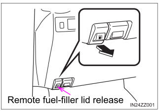
To open the fuel-filler lid, pull the remote fuel-filler lid release.