Toyota Yaris: Audio / Video / Pillar Speaker
Components
COMPONENTS
ILLUSTRATION
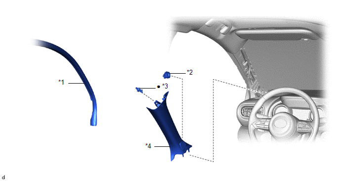
| *1 | NO. 1 ROOF HEADLINIG MOULDING | *2 | FRONT NO. 2 SPEAKER ASSEMBLY |
| *3 | FRONT PILLAR GARNISH CLIP | *4 | FRONT PILLAR GARNISH |
| ● | Non-reusable part | - | - |
Removal
REMOVAL
CAUTION / NOTICE / HINT
HINT:
- Use the same procedure for the RH and LH sides.
- The procedure listed below is for the LH side.
PROCEDURE
1. DISCONNECT NO. 1 ROOF HEADLINIG MOULDING
Click here

2. REMOVE FRONT PILLAR GARNISH
Click here

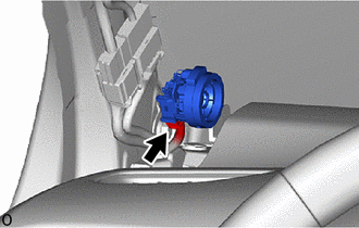
3. REMOVE FRONT NO. 2 SPEAKER ASSEMBLY
| (a) Disconnect the connector to remove the front No. 2 speaker assembly. |
|

Inspection
INSPECTION
PROCEDURE
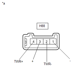
1. INSPECT FRONT NO. 2 SPEAKER ASSEMBLY (for RH Side)
(a) Check the resistance.
| (1) Measure the resistance according to the value(s) in the table below. Standard Resistance:
If the result is not as specified, replace the front No. 2 speaker assembly. |
|
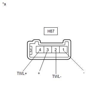
2. INSPECT FRONT NO. 2 SPEAKER ASSEMBLY (for LH Side)
(a) Check the resistance.
| (1) Measure the resistance according to the value(s) in the table below. Standard Resistance:
If the result is not as specified, replace the front No. 2 speaker assembly. |
|
Installation
INSTALLATION
CAUTION / NOTICE / HINT
HINT:
- Use the same procedure for the RH and LH sides.
- The procedure listed below is for the LH side.
PROCEDURE
1. INSTALL FRONT NO. 2 SPEAKER ASSEMBLY
| (a) Connect the connector to install the front No. 2 speaker assembly. |
|
2. INSTALL FRONT PILLAR GARNISH
Click here

3. CONNECT NO. 1 ROOF HEADLINIG MOULDING
Click here

 Installation
INSTALLATION PROCEDURE 1. INSTALL RADIO SETTING CONDENSER (a) Engage the claw to install a new terminal cover to the wire harness. NOTICE:
Make sure to hold the crimping side of the terminal when installing the wire harness to the terminal cover...
 Quarter Trim Speaker
ComponentsCOMPONENTS ILLUSTRATION
*1 REAR SPEAKER ASSEMBLY - - RemovalREMOVAL CAUTION / NOTICE / HINT HINT:
Use the same procedure for the RH and LH sides...
Other information:
Toyota Yaris XP210 (2020-2026) Reapir and Service Manual: ID-BOX Component Internal Failure (B278D96)
DESCRIPTION When the certification ECU (smart key ECU assembly) detects an input signal indicating that the vehicle is equipped with an ID code box even though the ID code box is not registered, the certification ECU (smart key ECU assembly) stores this DTC...
Toyota Yaris XP210 (2020-2026) Reapir and Service Manual: Installation
INSTALLATION PROCEDURE 1. INSTALL TIMING CHAIN COVER OIL SEAL Click here 2. INSTALL TIMING CHAIN COVER ASSEMBLY (a) Install 2 new O-rings to the cylinder block sub-assembly. (b) Clean the contact surfaces of the timing chain cover assembly, oil pan sub-assembly and cylinder block sub-assembly, and confirm that no oil, moisture, or other foreign matter is on the surfaces...
Categories
- Manuals Home
- Toyota Yaris Owners Manual
- Toyota Yaris Service Manual
- G16e-gts (engine Mechanical)
- Adjustment
- Engine & Hybrid System
- New on site
- Most important about car
Fuel Gauge
The fuel gauge shows approximately how much fuel is remaining in the tank when the ignition is switched ON. We recommend keeping the tank over 1/4 full.
