Toyota Yaris: Front Seatback Heater / Removal
REMOVAL
CAUTION / NOTICE / HINT
CAUTION:
-
Be sure to read Precaution thoroughly before servicing.
Click here

-
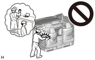
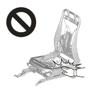
Wear protective gloves. Sharp areas on the parts may injure your hands.
HINT:
-
When the cable is disconnected / reconnected to the auxiliary battery terminal, systems temporarily stop operating. However, each system has a function that completes learning the first time the system is used.
-
Learning completes when vehicle is driven
Effect/Inoperative Function When Necessary Procedures are not Performed
Effect/Inoperative Function When Necessary Procedures are not Performed
Link
Lane tracing assist system
Drive the vehicle straight ahead at 35 km/h (22 mph) or more for 5 seconds or more.

Pre-collision system
Stop and start system
Drive the vehicle until stop and start control is permitted (approximately 5 to 60 minutes)

-
Learning completes when vehicle is operated normally
Effect/Inoperative Function When Necessary Procedures are not Performed
Effect/Inoperative Function When Necessary Procedures are not Performed
Link
Power door lock control system
- Back door opener
Perform door unlock operation with door control switch or electrical key transmitter sub-assembly switch.

Air conditioning system
After the ignition switch is turned to ON, the servo motor standard position is recognized.
-
-
Learning completes when vehicle is driven
- Use the same procedure for the driver side and front passenger side.
- The procedure listed below is for the driver side.
PROCEDURE
1. REMOVE FRONT SEAT INNER BELT ASSEMBLY
Click here

2. REMOVE FRONT SEAT VERTICAL ADJUSTER HANDLE (for Driver Side)
Click here

3. REMOVE NO.1 RECLINING HINGE COVER
Click here

4. REMOVE RECLINING ADJUSTER RELEASE HANDLE
Click here

5. REMOVE SEAT ADJUSTER COVER CAP (for Driver Side)
Click here

6. REMOVE FRONT SEAT CUSHION SHIELD
Click here

7. REMOVE FRONT SEAT INNER CUSHION SHIELD
Click here

8. REMOVE SEPARATE TYPE FRONT SEATBACK ASSEMBLY
Click here

9. REMOVE FRONT SEATBACK BEZEL (for Sports Seat Type)
Click here

10. REMOVE FRONT SEAT HEADREST SUPPORT ASSEMBLY
Click here

11. REMOVE SEPARATE TYPE FRONT SEATBACK COVER WITH PAD
Click here

12. REMOVE SEPARATE TYPE FRONT SEATBACK COVER
Click here

13. REMOVE FRONT SEATBACK HEATER ASSEMBLY
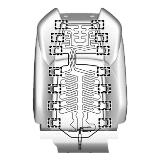
| (a) for Sporty Seat Type: (1) Remove the 14 tag pins and front seatback heater assembly from the separate type front seatback cover. |
|
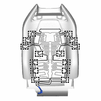
| (b) for Sports Seat Type: (1) Remove the 14 tag pins and front seatback heater assembly from the separate type front seatback cover. |
|
 Components
COMPONENTS ILLUSTRATION
*A for Driver Side *B for Front Passenger Side *1 FRONT SEAT VERTICAL ADJUSTER HANDLE *2 NO.1 RECLINING HINGE COVER *3 RECLINING ADJUSTER RELEASE HANDLE *4 SEAT ADJUSTER COVER CAP *5 FRONT SEAT CUSHION SHIELD *6 FRONT SEAT INNER CUSHION SHIELD ILLUSTRATION
*1 SEPARATE TYPE FRONT SEATBACK ASSEMBLY - -
Tightening torque for "Major areas involving basic vehicle performance such as moving/turning/stopping" : N*m (kgf*cm, ft...
 Inspection
INSPECTION PROCEDURE 1. INSPECT FRONT SEATBACK HEATER ASSEMBLY LH (a) Check the resistance. (1) Measure the resistance according to the value(s) in the table below...
Other information:
Toyota Yaris XP210 (2020-2026) Reapir and Service Manual: Vehicle Control History
VEHICLE CONTROL HISTORY CHECK VEHICLE CONTROL HISTORY (a) Connect the GTS to the DLC3. (b) Turn the ignition switch to ON. (c) Turn the GTS on. (d) Enter the following menus: Powertrain / Engine / Utility / Vehicle Control History (RoB). Powertrain > Engine > Utility Tester Display Vehicle Control History (RoB) Vehicle Control History (RoB) Item Code Tester Display Measurement Item Diagnostic Note X0600 Auxiliary Battery Voltage Low at Start History of low battery voltage at engine control system start - X0601 Auxiliary Battery Voltage Low at IG OFF History of low battery voltage when ignition switch off - X0602 Auxiliary Battery Discharge at IG OFF History of auxiliary battery becoming discharged when ignition switch off - X0603 Auxiliary Battery Discharge at Running History of auxiliary battery becoming discharged while vehicle being driven - X0606 Auxiliary Battery Voltage Low during Running History of low battery voltage while vehicle being driven - X0607 Auxiliary Battery Voltage High during Running History of high battery voltage while vehicle being driven - CLEAR VEHICLE CONTROL HISTORY (a) Connect the GTS to the DLC3...
Toyota Yaris XP210 (2020-2026) Reapir and Service Manual: Reassembly
REASSEMBLY PROCEDURE 1. INSTALL FUEL PUMP HINT: Perform "Inspection After Repair" after replacing the fuel pump. Click here (a) Install the fuel pump to the No. 1 cap. (b) Apply gasoline to a new O-ring. (c) Install the O-ring to the sub-assembly support...
Categories
- Manuals Home
- Toyota Yaris Owners Manual
- Toyota Yaris Service Manual
- Adjustment
- How to use USB mode
- Fuse Panel Description
- New on site
- Most important about car
Keys

To use the auxiliary key, press the knob and pull out the auxiliary key from the smart key.
