Toyota Yaris: Solar Sensor / On-vehicle Inspection
ON-VEHICLE INSPECTION
PROCEDURE
1. INSPECT AUTOMATIC LIGHT CONTROL SENSOR
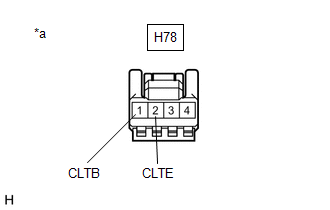
(a) Check the wire harness.
(1) Disconnect the automatic light control sensor.
| (2) Measure the voltage according to the value(s) in the table below. Standard Voltage:
If the specified condition is not met, replace the vehicle wire harness. |
|
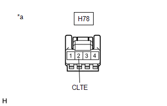
(b) Check the resistance.
| (1) Measure the resistance according to the value(s) in the table below. Standard Resistance:
If the specified condition is not met, replace the vehicle wire harness. |
|
(c) Check the automatic light control sensor.
(1) Connect the automatic light control sensor.
(2) Check the waveform. Use the oscilloscope and check the waveform in the terminal spaces.
NOTICE:
With the connector connected as is, check from the rear side of the connector.
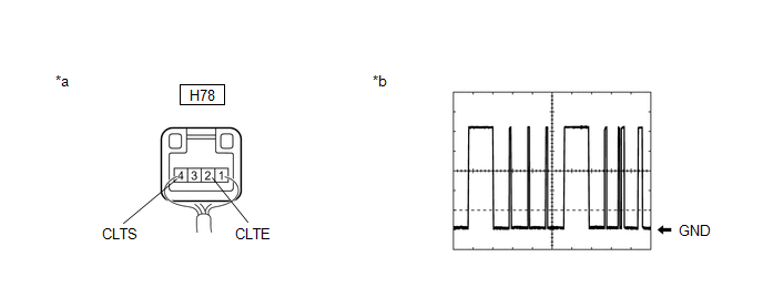
| *a | Component with harness connected (Automatic Light Control Sensor) | *b | Waveform |
OK:
| Tester Connection | Condition | Tool Setting | Specified Condition |
|---|---|---|---|
| H78-4 (CLTS) - H78-2 (CLTE) | Ignition switch on (IG) | 2 V/DIV.,10 ms/DIV. | Pulse generation (See waveform) |
HINT:
The communication waveform changes according to the surrounding brightness.
If the result is not as specified, the automatic light control sensor may be malfunctioning.
 Components
C..
 Removal
REMOVAL PROCEDURE 1. DISCONNECT NO. 1 ROOF HEADLINING MOULDING LH Click here
2. DISCONNECT NO. 1 ROOF HEADLINING MOULDING RH HINT: Use the same procedure as for the LH side...
Other information:
Toyota Yaris XP210 (2020-2026) Reapir and Service Manual: Freeze Frame Data
FREEZE FRAME DATA FREEZE FRAME DATA (a) When a DTC is stored, the AWD ECU assembly stores the current vehicle state as Freeze Frame Data. HINT: Freeze Frame Data at the time a DTC is stored: When the AWD ECU assembly stores data at the time a DTC is stored, no updates will be performed until the data is cleared...
Toyota Yaris XP210 (2020-2026) Reapir and Service Manual: Diagnosis System
DIAGNOSIS SYSTEM DIAGNOSIS FUNCTION (a) The diagnosis function turns off the cruise control indicator and displays a warning message when a malfunction is detected. When a malfunction is detected in the dynamic radar cruise control system, DTCs are stored in the ECM or millimeter wave radar sensor assembly...
Categories
- Manuals Home
- Toyota Yaris Owners Manual
- Toyota Yaris Service Manual
- To Set Speed
- How to use USB mode
- Opening and Closing the Liftgate/Trunk Lid
- New on site
- Most important about car
Keys

To use the auxiliary key, press the knob and pull out the auxiliary key from the smart key.
