Toyota Yaris: Rain Sensor / On-vehicle Inspection
ON-VEHICLE INSPECTION
PROCEDURE
1. INSPECT RAIN SENSOR
(a) Remove the rain sensor cover.
Click here
.gif)
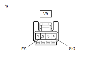
(b) Disconnect the rain sensor connector.
| (c) Measure the voltage according to the value(s) in the table below. Standard Voltage:
If the result is not as specified, repair or replace the harness or connector. |
|
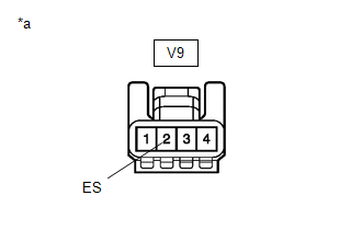
| (d) Measure the resistance according to the value(s) in the table below. Standard Resistance:
If the result is not as specified, repair or replace the harness or connector. |
|
(e) Reconnect the rain sensor connector.
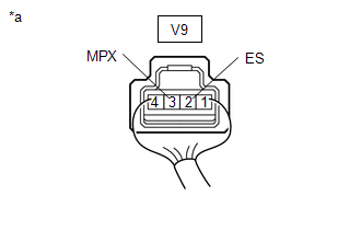
(f) Connect an oscilloscope to the rain sensor connector.
| (g) Check for pulses. OK:
If the result is not as specified, replace the rain sensor. |
|
(h) Install the rain sensor cover.
Click here
 Components
C..
 Removal
REMOVAL PROCEDURE 1. REMOVE RAIN SENSOR COVER (a) Disengage the claws and guide to remove the rain sensor cover.
2. REMOVE RAIN SENSOR (a) Release the stopper by pulling it out as shown in the illustration...
Other information:
Toyota Yaris XP210 (2020-2026) Reapir and Service Manual: Components
COMPONENTS ILLUSTRATION *1 CENTER LOWER INSTRUMENT COVER *2 LOWER INSTRUMENT PANEL FINISH PANEL *3 SWITCH HOLE BASE SUB-ASSEMBLY *4 SHIFT LEVER KNOB SUB-ASSEMBLY *5 CONSOLE BOX ASSEMBLY - - ILLUSTRATION *1 FRONT DOOR SCUFF PLATE LH *2 COWL SIDE TRIM BOARD LH *3 NO...
Toyota Yaris XP210 (2020-2026) Reapir and Service Manual: Installation
INSTALLATION PROCEDURE 1. INSTALL RADIATOR DRAIN COCK PLUG (a) Install the O-ring to the radiator drain cock plug. NOTICE: Replace the O-ring if it is damaged. (b) Install the radiator drain cock plug. 2. INSTALL LOWER RADIATOR SUPPORT (a) Install the 2 lower radiator supports to the radiator assembly...
Categories
- Manuals Home
- Toyota Yaris Owners Manual
- Toyota Yaris Service Manual
- Removal
- Adjustment
- G16e-gts (engine Mechanical)
- New on site
- Most important about car
Break-In Period
No special break-in is necessary, but a few precautions in the first 600 miles (1,000 km) may add to the performance, economy, and life of the vehicle.
Do not race the engine. Do not maintain one constant speed, either slow or fast, for a long period of time. Do not drive constantly at full-throttle or high engine rpm for extended periods of time. Avoid unnecessary hard stops. Avoid full-throttle starts.