Toyota Yaris: Pre-collision System / Lost Communication with Image Processing Module "A" Missing Message (U023A87)
DESCRIPTION
The millimeter wave radar sensor assembly is connected to the forward recognition camera via the CAN communication line. If the millimeter wave radar sensor assembly receives signals indicating that its communication with the forward recognition camera is abnormal, the millimeter wave radar sensor assembly stores DTC U023A87.
| DTC No. | Detection Item | DTC Detection Condition | Trouble Area |
|---|---|---|---|
| U023A87 | Lost Communication with Image Processing Module "A" Missing Message | When the ignition switch is ON for 3 seconds or more, a forward recognition camera communication malfunction continues for approximately 3 seconds or more. |
|
| Pattern | DTC output part name (Display on GTS) | Suspected Area (Malfunction Status) | |||
|---|---|---|---|---|---|
| Millimeter Wave Radar Sensor Assembly | Forward Recognition Camera | ||||
| Pre-Collision System | Radar Cruise2 | Lane Control | Forward Recognition Camera (Front Lighting Control) | ||
| U023A87 | U023A87 | U023587 | U023587 | ||
|
○: DTC is output
-: DTC is not output | |||||
| Pattern 1 | ○ | ○ | ○ | ○ | Harness or connector (Open or short) |
| Millimeter wave radar sensor assembly (Internal malfunction) | |||||
| Forward recognition camera (Internal malfunction) | |||||
| Pattern 2 | ○ | ○ | - | - | Millimeter wave radar sensor assembly (Internal malfunction) |
| Forward recognition camera (Internal malfunction) | |||||
HINT:
If the DTCs are output simultaneously, the inspection area can be narrowed down.
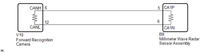
WIRING DIAGRAM
CAUTION / NOTICE / HINT
NOTICE:
- When replacing the millimeter wave radar sensor assembly, always replace it with a new one. If a millimeter wave radar sensor assembly which was installed to another vehicle is used, the information stored in the millimeter wave radar sensor assembly will not match the information from the vehicle and a DTC may be stored.
-
When the millimeter wave radar sensor assembly has been replaced with a new one, it is necessary to perform millimeter wave radar sensor assembly beam axis alignment and to clear the vehicle control history. Before performing the Driving Adjustment, make sure to read Before Starting Driving Adjustment.
HINT:
Beam axis alignment of the millimeter wave radar sensor assembly can be performed using either Triangle Target, Flat Surface Target or Driving Adjustment.
Triangle Target: Click here

Flat Surface Target: Click here

Driving Adjustment: Click here

- When replacing the forward recognition camera, always replace it with a new one. If a forward recognition camera which was installed to another vehicle is used, the information stored in the forward recognition camera will not match the information from the vehicle and a DTC may be stored.
-
When the forward recognition camera is replaced with a new one or the windshield glass is replaced or removed/installed, make sure to read Before Starting Adjustment, then perform optical axis alignment for the forward recognition camera and clear the vehicle control history for each system.
HINT:
Forward recognition camera adjustment can be performed by using either One Time Recognition, Sequential Recognition or Driving Adjustment.
One Time Recognition: Click here

Sequential Recognition: Click here

Driving Adjustment: Click here

-
After the ignition switch is turned off, there may be a waiting time before disconnecting the negative (-) auxiliary battery terminal. Click here

HINT:
When disconnecting and reconnecting the battery, there is an automatic learning function that completes learning when the respective system is used.
Click here

HINT:
If there are communication malfunctions for systems other than the millimeter wave radar sensor assembly and forward recognition camera, refer to "HOW TO PROCEED WITH TROUBLESHOOTING" for the CAN Communication System.
Click here

PROCEDURE
| 1. | CHECK FOR DTC |
(a) Read each DTC and check the diagnosis pattern using the table below.
Body Electrical > Pre-Collision System > Trouble Codes Powertrain > Radar Cruise2 > Trouble Codes Chassis > Lane Control > Trouble Codes Body Electrical > Front Recognition Camera (Front Lighting Control) > Trouble Codes| Pattern | DTC output part name (Display on GTS / Output DTC) | |||
|---|---|---|---|---|
| Radar Cruise2 | Pre-Collision System | Lane Control | Forward Recognition Camera (Front Lighting Control) | |
| Pattern 1 | U023A87 | U023A87 | U023587 | U023587 |
| Pattern 2 | U023A87 | U023A87 | - | - |
| Result | Proceed to |
|---|---|
| Pattern 1 | A |
| Pattern 2 | B |
| B |
 | GO TO STEP 4 |
|

| 2. | CHECK CAN MAIN WIRE (MILLIMETER WAVE RADAR SENSOR ASSEMBLY) |
(a) Disconnect the cable from the negative (-) auxiliary battery terminal.
(b) Disconnect the B8 millimeter wave radar sensor assembly connector.
(c) Measure the resistance according to the value(s) in the table below.
Standard Resistance:| Tester Connection | Condition | Specified Condition |
|---|---|---|
| B8-5 (CA1P) - B8-6 (CA1N) | Cable disconnected from negative (-) auxiliary battery terminal | 108 to 132 Ω |
| B8-5 (CA1P) - Body ground | Cable disconnected from negative (-) auxiliary battery terminal | 200 Ω or higher |
| B8-6 (CA1N) - Body ground | Cable disconnected from negative (-) auxiliary battery terminal | 200 Ω or higher |
| B8-5 (CA1P) - +B | Cable disconnected from negative (-) auxiliary battery terminal | 6 kΩ or higher |
| B8-6 (CA1N) - +B | Cable disconnected from negative (-) auxiliary battery terminal | 6 kΩ or higher |
| OK |
 | REPLACE MILLIMETER WAVE RADAR SENSOR ASSEMBLY |
|

| 3. | CHECK CAN MAIN WIRE (FORWARD RECOGNITION CAMERA) |
(a) Disconnect the cable from the negative (-) auxiliary battery terminal.
(b) Disconnect the V10 forward recognition camera connector.
(c) Measure the resistance according to the value(s) in the table below.
Standard Resistance:| Tester Connection | Condition | Specified Condition |
|---|---|---|
| V10-6 (CANH) - V10-12 (CANL) | Cable disconnected from negative (-) auxiliary battery terminal | 108 to 132 Ω |
| V10-6 (CANH) - Body ground | Cable disconnected from negative (-) auxiliary battery terminal | 200 Ω or higher |
| V10-12 (CANL) - Body ground | Cable disconnected from negative (-) auxiliary battery terminal | 200 Ω or higher |
| V10-6 (CANH) - +B | Cable disconnected from negative (-) auxiliary battery terminal | 6 kΩ or higher |
| V10-12 (CANL) - +B | Cable disconnected from negative (-) auxiliary battery terminal | 6 kΩ or higher |
| OK |
 | REPLACE FORWARD RECOGNITION CAMERA |
| NG |
 | REPAIR OR REPLACE CAN BUS SUB LINE OR CONNECTOR |
| 4. | CHECK FORWARD RECOGNITION CAMERA |
(a) Disconnect the B8 millimeter wave radar sensor assembly connector.
(b) Measure the waveform according the table below.
Measurement Condition:| Tester Connection | Condition | Tool Setting | Specified Condition |
|---|---|---|---|
| B8-5 (CA1P) - B8-6 (CA1N) | Ignition switch ON | 1V/DIV., 100μs./DIV. | Waveform generation |
| OK |
 | REPLACE MILLIMETER WAVE RADAR SENSOR ASSEMBLY |
| NG |
 | REPLACE FORWARD RECOGNITION CAMERA |
 Lost Communication with ECM/PCM "A" Missing Message (U010087,U010187,U012687,U012987,U015587)
DESCRIPTION The following DTCs are stored when there is a communication malfunction between the millimeter wave radar sensor and each sensor or ECU. DTC No...
 Internal Control Module Software Incompatibility Not Programmed (U030051,U030057)
DESCRIPTION The millimeter wave radar sensor assembly receives vehicle information (Conv/HV/EV) or vehicle information (transmission type) from the ECM via the CAN communication line...
Other information:
Toyota Yaris XP210 (2020-2026) Reapir and Service Manual: Zero Point Calibration of Steering Angle Sensor Malfunction (X20D7)
DESCRIPTION Code Tester Display Measurement Item Trouble Area RoB Output from X20D7 Zero Point Calibration of Steering Angle Sensor Malfunction History of the steering angle sensor zero point calibration position differing from the stored value Poor adjustment of the center position of the steering wheel Poor adjustment of wheel alignment Brake CAUTION / NOTICE / HINT NOTICE: After performing the inspection, check and clear the vehicle control history (RoB)...
Toyota Yaris XP210 (2020-2026) Reapir and Service Manual: Diagnostic Trouble Code Chart
D..
Categories
- Manuals Home
- Toyota Yaris Owners Manual
- Toyota Yaris Service Manual
- Diagnostic Trouble Code Chart
- Fuel Gauge
- Engine & Hybrid System
- New on site
- Most important about car
Fuel-Filler Lid and Cap
WARNING
When removing the fuel-filler cap, loosen the cap slightly and wait for any hissing to stop, then remove it
Fuel spray is dangerous. Fuel can burn skin and eyes and cause illness if ingested. Fuel spray is released when there is pressure in the fuel tank and the fuel-filler cap is removed too quickly.