Toyota Yaris: Air Conditioning System / Lost Communication with Air Inlet Damper Control Servo Motor LIN Missing Message (B143A87)
DESCRIPTION
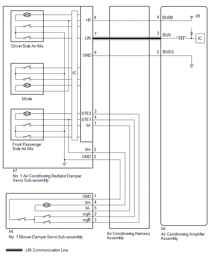
The air conditioning harness assembly and No. 1 air conditioning radiator damper servo sub-assembly connect the air conditioning amplifier assembly and the No. 1 blower damper servo sub-assembly. The air conditioning amplifier assembly supplies power and sends operation instructions to No. 1 blower damper servo sub-assembly through the air conditioning harness assembly and No. 1 air conditioning radiator damper servo sub-assembly. The No. 1 blower damper servo sub-assembly sends pulse signals to inform the air conditioning amplifier assembly of the damper position.
| DTC No. | Detection Item | DTC Detection Condition | Trouble Area | Memory |
|---|---|---|---|---|
| B143A87 | Lost Communication with Air Inlet Damper Control Servo Motor LIN Missing Message | Diagnosis Condition:
Malfunction Status:
Detection Time:
|
| Memorized |
| Vehicle Condition | |||
|---|---|---|---|
| Pattern 1 | Pattern 2 | ||
| Diagnosis Condition | Ignition switch ON | ○ | ○ |
| Malfunction | Error communication with No. 1 blower damper servo sub-assembly | ○ | - |
| Lost communication with No. 1 blower damper servo sub-assembly | - | ○ | |
| Detection Time | Continuously for 10 seconds or more | Continuously for 10 seconds or more | |
| Trip Count | 1 trip | 1 trip | |
HINT:
If the conditions of either of these patterns are detected, a DTC will be stored.
WIRING DIAGRAM
PROCEDURE
| 1. | CHECK FOR DTC |
(a) Check for DTCs.
Body Electrical > Air Conditioner > Trouble Codes| Result | Proceed to |
|---|---|
| B142A88 is output | A |
| B142A88 is not output | B |
| A |
 | GO TO DTC B142A88 |
|

| 2. | INSPECT AIR CONDITIONING HARNESS ASSEMBLY |
(a) Disconnect the h7 No. 1 air conditioning radiator damper servo sub-assembly connector.
(b) Disconnect the h4 No. 1 blower damper servo sub-assembly connector.
(c) Measure the resistance according to the value(s) in the table below.
Standard Resistance:
| Tester Connection | Condition | Specified Condition |
|---|---|---|
| h7-1 (M-) - h4-5 (M-) | Always | Below 1 Ω |
| h7-2 (M+) - h4-4 (M+) | Always | Below 1 Ω |
| h7-3 (STE2) - h4-3 (sigB) | Always | Below 1 Ω |
| h7-4 (STE1) - h4-2 (sigA) | Always | Below 1 Ω |
| h7-5 (GND) - h4-1 (GND) | Always | Below 1 Ω |
| h7-1 (M-) or h4-5 (M-) - Other terminals and body ground | Always | 10 kΩ or higher |
| h7-2 (M+) or h4-4 (M+) - Other terminals and body ground | Always | 10 kΩ or higher |
| h7-3 (STE2) or h4-3 (sigB) - Other terminals and body ground | Always | 10 kΩ or higher |
| h7-4 (STE1) or h4-2 (sigA) - Other terminals and body ground | Always | 10 kΩ or higher |
| OK |
 | REPLACE NO. 1 BLOWER DAMPER SERVO SUB-ASSEMBLY |
| NG |
 | REPLACE AIR CONDITIONING HARNESS ASSEMBLY |
 Servo Motor LIN Communication Bus off (B142A88)
DESCRIPTION The air conditioning harness assembly connects the air conditioning amplifier assembly and the servo motors. The air conditioning amplifier assembly supplies power and sends operation instructions to each servo motor through the air conditioning harness assembly...
 Air Inlet Damper Control Servo Motor Actuator Stuck Off (B143B7F)
DESCRIPTION The No. 1 blower damper servo sub-assembly sends pulse signals to inform the air conditioning amplifier assembly of the damper position. The air conditioning amplifier assembly activates the motor (normal or reverse) based on these signals to move the air inlet damper to the appropriate position, which controls the air inlet switching...
Other information:
Toyota Yaris XP210 (2020-2025) Reapir and Service Manual: Rear Brake Flexible Hose
ComponentsCOMPONENTS ILLUSTRATION *1 REAR FLEXIBLE HOSE *2 GASKET *3 UNION BOLT *4 BRAKE LINE Tightening torque for "Major areas involving basic vehicle performance such as moving/turning/stopping": N*m (kgf*cm, ft.*lbf) * For use with a union nut wrench ● Non-reusable part - - InstallationINSTALLATION CAUTION / NOTICE / HINT HINT: Use the same procedure for the RH side and LH side...
Toyota Yaris XP210 (2020-2025) Reapir and Service Manual: Parts Location
PARTS LOCATION ILLUSTRATION *1 COMPRESSOR WITH PULLEY ASSEMBLY *2 AIR CONDITIONER PRESSURE SENSOR *3 POWER STEERING ECU ASSEMBLY *4 NO. 1 ENGINE ROOM RELAY BLOCK AND NO. 1 JUNCTION BLOCK ASSEMBLY - ECU-IGP NO. 3 FUSE *5 ECM *6 THERMISTOR ASSEMBLY *7 COOLER CONDENSER ASSEMBLY - - ILLUSTRATION *1 COMBINATION METER ASSEMBLY *2 AUTOMATIC LIGHT CONTROL SENSOR *3 ENGINE STOP AND START ECU *4 AIR CONDITIONING CONTROL ASSEMBLY *5 AIR CONDITIONING AMPLIFIER ASSEMBLY *6 COOLER THERMISTOR (ROOM TEMPERATURE SENSOR) *7 DLC3 *8 POWER DISTRIBUTION BOX ASSEMBLY - ECU-B NO...
Categories
- Manuals Home
- Toyota Yaris Owners Manual
- Toyota Yaris Service Manual
- Power Integration No.1 System Missing Message (B235287,B235587,B235787-B235987)
- Headlights
- How to use USB mode
- New on site
- Most important about car
Supplemental Restraint System (SRS) Precautions
The front and side supplemental restraint systems (SRS) include different types of air bags. Please verify the different types of air bags which are equipped on your vehicle by locating the “SRS AIRBAG” location indicators. These indicators are visible in the area where the air bags are installed.
The air bags are installed in the following locations:
The steering wheel hub (driver air bag) The front passenger dashboard (front passenger air bag) The outboard sides of the front seatbacks (side air bags) The front and rear window pillars, and the roof edge along both sides (curtain air bags)