Toyota Yaris: Lighting System / Interior Light Circuit
DESCRIPTION
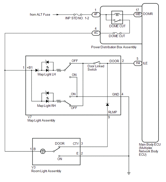
The main body ECU (multiplex network body ECU) controls the operation of the following lights:
- Map Light Assembly
- Room Light Assembly
WIRING DIAGRAM
CAUTION / NOTICE / HINT
NOTICE:
- Inspect the fuses for circuits related to this system before performing the following procedure.
-
Before replacing the main body ECU (multiplex network body ECU), refer to Registration.
Click here

HINT:
The DOME CUT relay supplies power to the interior lights. If all the lights that use power from the DOME CUT relay do not turn on, check the interior light auto cut circuit first.
Click here

PROCEDURE
| 1. | PERFORM ACTIVE TEST USING GTS |
(a) Perform the Active Test according to the display on the GTS.
Body Electrical > Main Body > Active Test| Tester Display | Measurement Item | Control Range | Diagnostic Note |
|---|---|---|---|
| Illuminated Entry System | Turns on the lights that are controlled by the illuminated entry system*1 | OFF or ON | Perform the Active Test with DOOR switch in the map light assembly and room light assembly turned on. |
-
*1: Refer to System Description for the lights that are controlled by the illuminated entry system.
Click here

| Tester Display |
|---|
| Illuminated Entry System |
OK:
All lights that are controlled by the illuminated entry system come on.
| Result | Proceed to |
|---|---|
| OK | A |
| NG (Map light does not come on) | B |
| NG (Room light does not come on) | C |
| NG (Map light and room light does not come on) | D |
| A |
 | PROCEED TO NEXT SUSPECTED AREA SHOWN IN PROBLEM SYMPTOMS TABLE |
| C |
 | GO TO STEP 4 |
| D |
 | GO TO STEP 5 |
|

| 2. | INSPECT MAP LIGHT ASSEMBLY |
Click here

| NG |
 | REPLACE MAP LIGHT ASSEMBLY |
|

| 3. | CHECK HARNESS AND CONNECTOR (MAP LIGHT ASSEMBLY - POWER DISTRIBUTION BOX ASSEMBLY) |
(a) Disconnect the 4C power distribution box assembly connector.
(b) Disconnect the H4 main body ECU (multiplex network body ECU) connector.
(c) Measure the resistance according to the value(s) in the table below.
Standard Resistance:
| Tester Connection | Condition | Specified Condition |
|---|---|---|
| V7-1(+B1) - 4C-4 | Always | Below 1 Ω |
| OK |
 | USE SIMULATION METHOD TO CHECK |
| NG |
 | REPAIR OR REPLACE HARNESS OR CONNECTOR |
| 4. | CHECK HARNESS AND CONNECTOR (MAP LIGHT ASSEMBLY - ROOM LIGHT ASSEMBLY) |
(a) Disconnect the 4C power distribution box assembly connector.
(b) Disconnect the V3 room light assembly connector.
(c) Disconnect the V7 map light assembly connector.
(d) Measure the resistance according to the value(s) in the table below.
Standard Resistance:
| Tester Connection | Condition | Specified Condition |
|---|---|---|
| V3-1 (B) - V7-1 (+B1) | Always | Below 1 Ω |
| V3-3 (CTY) - V7-9 (RLMP) | Always | Below 1 Ω |
| OK |
 | USE SIMULATION METHOD TO CHECK |
| NG |
 | REPAIR OR REPLACE HARNESS OR CONNECTOR |
| 5. | INSPECT MAP LIGHT ASSEMBLY |
Click here

| NG |
 | REPLACE MAP LIGHT ASSEMBLY |
|

| 6. | CHECK HARNESS AND CONNECTOR (MAP LIGHT ASSEMBLY - POWER DISTRIBUTION BOX ASSEMBLY) |
(a) Disconnect the 4C power distribution box assembly connector.
(b) Disconnect the H4 main body ECU (multiplex network body ECU) connector.
(c) Measure the resistance according to the value(s) in the table below.
Standard Resistance:
| Tester Connection | Condition | Specified Condition |
|---|---|---|
| V7-1(+B1) - 4C-4 | Always | Below 1 Ω |
| V7-2 (DOOR) - H4-5 (ILE) | Always | Below 1 Ω |
| V7-1(+B1) or 4C-4 - Body ground | Always | 10 kΩ or higher |
| V7-2 (DOOR) or H4-5 (ILE) - Body ground | Always | 10 kΩ or higher |
| OK |
 | REPLACE MAIN BODY ECU (MULTIPLEX NETWORK BODY ECU) |
| NG |
 | REPAIR OR REPLACE HARNESS OR CONNECTOR |
 Back Door Courtesy Switch Circuit
DESCRIPTION The main body ECU (multiplex network body ECU) receives a back door open/closed signal from the back door courtesy light switch (back door lock assembly)...
 Interior Light Auto Cut Circuit
DESCRIPTION The main body ECU (multiplex network body ECU) controls operation of the DOME CUT relay in order to supply power to the interior lights. When the battery saving function operates while the interior lights are on, the main body ECU (multiplex network body ECU) opens the DOME CUT relay to turn off the lights...
Other information:
Toyota Yaris XP210 (2020-2026) Reapir and Service Manual: Installation
INSTALLATION PROCEDURE 1. INSTALL AIR CONDITIONING AMPLIFIER ASSEMBLY (a) Connect the 3 connectors. (b) Engage the guide to install the air conditioning amplifier assembly. (c) Install the 3 screws. (d) Install the front floor carpet assembly with the 2 clips as shown in the illustration...
Toyota Yaris XP210 (2020-2026) Reapir and Service Manual: System Diagram
S..
Categories
- Manuals Home
- Toyota Yaris Owners Manual
- Toyota Yaris Service Manual
- G16e-gts (engine Mechanical)
- Immobilizer System
- To Set Speed
- New on site
- Most important about car
Front Seat Belt Pretensioners
The front seat belt pretensioners are designed to deploy in moderate or severe frontal, near frontal collisions.
In addition, the pretensioners operate when a side collision or a rollover accident is detected. The pretensioners operate differently depending on what types of air bags are equipped. For more details about the seat belt pretensioner operation, refer to the SRS Air Bag Deployment Criteria.