Toyota Yaris: Front Evaporator Temperature Sensor / Installation
INSTALLATION
PROCEDURE
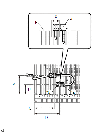
1. INSTALL NO. 1 COOLER THERMISTOR
| (a) Install the No. 1 cooler thermistor as shown in the illustration. Installation Position:
NOTICE:
|
|
2. INSTALL NO. 1 COOLER EVAPORATOR SUB-ASSEMBLY
Click here

3. INSTALL HEATER RADIATOR UNIT SUB-ASSEMBLY
Click here

4. INSTALL HEATER CLAMP
Click here

5. INSTALL COOLER EXPANSION VALVE
Click here

6. INSTALL COOLER PIPE GROMMET
Click here

7. INSTALL NO. 2 AIR DUCT
Click here

8. INSTALL BLOWER ASSEMBLY
Click here

 Inspection
INSPECTION PROCEDURE 1. INSPECT NO. 1 COOLER THERMISTOR (a) Check the resistance. (1) Measure the resistance according to the value(s) in the table below...
 Refrigerant (for Hfc-134a(r134a))
ReplacementREPLACEMENT PROCEDURE 1. RECOVER REFRIGERANT FROM REFRIGERATION SYSTEM (a) Turn the ignition switch ON. (b) Operate the compressor under the conditions shown below: Item Condition Operating time 3 minutes or more Temperature setting Max cool Blower speed High Engine Idling A/C switch ON This causes most of the compressor oil from the various components of the A/C system to collect in the compressor...
Other information:
Toyota Yaris XP210 (2020-2026) Owner's Manual: Installation on rear outboard seats
First, adjust the front seat to allow clearance between the child-restraint system and the front seat. Make sure the seatback is securely latched by pushing it back until it is fully locked. Expand the open seams on the rear of the seat bottom slightly to verify the locations of the LATCH lower anchors...
Toyota Yaris XP210 (2020-2026) Reapir and Service Manual: Installation
INSTALLATION CAUTION / NOTICE / HINT HINT: Use the same procedure for the RH side and LH side. The procedure listed below is for the LH side. PROCEDURE 1. INSTALL REAR SEAT OUTER BELT ASSEMBLY (a) Inspect the rear seat outer belt assembly. Click here (b) Engage the guides to temporarily install the rear outer belt assembly...
Categories
- Manuals Home
- Toyota Yaris Owners Manual
- Toyota Yaris Service Manual
- How to use USB mode
- To Set Speed
- Maintenance
- New on site
- Most important about car
Fuel-Filler Lid and Cap
WARNING
When removing the fuel-filler cap, loosen the cap slightly and wait for any hissing to stop, then remove it
Fuel spray is dangerous. Fuel can burn skin and eyes and cause illness if ingested. Fuel spray is released when there is pressure in the fuel tank and the fuel-filler cap is removed too quickly.