Toyota Yaris: Oil Pump / Installation
INSTALLATION
PROCEDURE
1. INSTALL TIMING CHAIN COVER OIL SEAL
Click here

2. INSTALL TIMING CHAIN COVER ASSEMBLY
| (a) Install 2 new O-rings to the cylinder block sub-assembly. |
|
(b) Clean the contact surfaces of the timing chain cover assembly, oil pan sub-assembly and cylinder block sub-assembly, and confirm that no oil, moisture, or other foreign matter is on the surfaces.
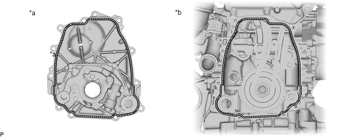
| *a | Timing Chain Cover Assembly Side | *b | Engine Assembly Side |
(c) Clean the contact surfaces of the timing chain cover assembly, oil pan sub-assembly and cylinder block sub-assembly, and confirm that no oil, moisture, or other foreign matter is on the surfaces.

| *a | 2.5 to 3.5 mm (0.0984 to 0.138 in.) | *b | 10 mm (0.394 in.) |
| *c | 4.0 to 6.0 mm (0.157 to 0.236 in.) | *d | 3.0 to 4.0 mm (0.118 to 0.157 in.) |
 | Seal Packing | - | - |
Seal Packing:
Toyota Genuine Seal Packing Black, Three Bond 1207B or equivalent
NOTICE:
- Clean the surfaces with non-residue solvent before applying seal packing.
- Install the timing chain cover assembly within 3 minutes and tighten the bolts within 10 minutes of applying seal packing.
- Do not add oil for at least 2 hours after installation.
- Do not start the engine for at least 2 hours after installation.
- Make sure that the diameter at the start and end of each line of seal packing is 5 +/- 2 mm (0.197 +/- 0.0787 in.).
(d) Align the oil pump drive rotor groove of the timing chain cover assembly.

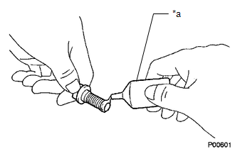
| (e) Apply adhesive to 5 and a half threads or more of the end of the bolts (A, B). Adhesive: Toyota Genuine Adhesive 1344, Three Bond 1344 or equivalent |
|
| (f) Temporarily install the timing chain cover assembly with the 11 bolts and a new bolt (C) and seal washer. Bolt Length:
|
|
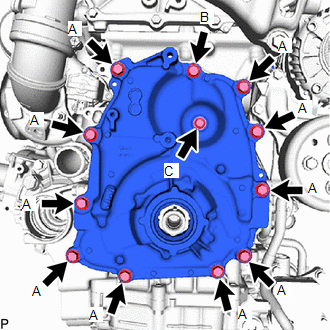
(g) Install the timing chain cover assembly with the 11 bolts and a new bolt (C) and seal washer in the order shown in the illustration.
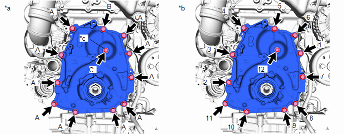
| *a | Torque | *b | Bolt Tightening Order |
| *c | Seal Washer | - | - |
Torque:
Bolt (A), (B) :
21 N·m {214 kgf·cm, 15 ft·lbf}
Bolt (C) :
10 N·m {102 kgf·cm, 7 ft·lbf}
3. INSTALL CRANKSHAFT PULLEY
Click here

4. INSTALL TIMING GEAR COVER INSULATOR
(a) Install the timing gear cover insulator to the timing chain cover assembly.
5. INSTALL V-RIBBED BELT TENSIONER ASSEMBLY
Click here

6. INSTALL ENGINE WIRE
(a) Install the engine wire to the timing chain cover assembly with the bolt.
Torque:
10 N·m {102 kgf·cm, 7 ft·lbf}
7. INSTALL NO. 2 AIR HOSE
(a) Install the No. 2 air hose to the turbocharger sub-assembly and tighten the hose clamp.
Torque:
6.0 N·m {61 kgf·cm, 53 in·lbf}
8. INSTALL NO. 1 AIR TUBE
(a) Install the 2 bolts.
Torque:
7.0 N·m {71 kgf·cm, 62 in·lbf}
(b) Install the No. 1 air tube to the No. 2 air hose, No. 3 air hose and tighten the hose clamp.
Torque:
6.0 N·m {61 kgf·cm, 53 in·lbf}
9. INSTALL COMPRESSOR ASSEMBLY WITH PULLEY
Click here

10. INSTALL FAN AND GENERATOR V BELT
Click here

11. INSTALL NO. 1 ENGINE UNDER COVER ASSEMBLY
Click here

12. INSTALL ENGINE UNDER COVER RH
Click here

13. INSTALL FRONT WHEELS
Click here

 Removal
REMOVAL PROCEDURE 1. REMOVE FRONT WHEELS Click here
2. REMOVE ENGINE UNDER COVER RH Click here
3. REMOVE NO. 1 ENGINE UNDER COVER ASSEMBLY Click here
4...

Other information:
Toyota Yaris XP210 (2020-2026) Reapir and Service Manual: Removal
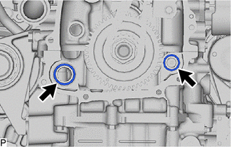
REMOVAL CAUTION / NOTICE / HINT NOTICE: To avoid degrading the precision of the assembly, do not loosen or remove the 2 bolts shown in the illustration. If the bolts have been loosened or removed, use the following procedure to reassemble the parts...
Toyota Yaris XP210 (2020-2026) Reapir and Service Manual: Vehicle Control History
VEHICLE CONTROL HISTORY CHECK VEHICLE CONTROL HISTORY (a) Connect the GTS to the DLC3. (b) Turn the ignition switch to ON. (c) Turn the GTS on. (d) Enter the following menus: Powertrain / Engine / Utility / Vehicle Control History (RoB). Powertrain > Engine > Utility Tester Display Vehicle Control History (RoB) Vehicle Control History (RoB) Item Code Tester Display Measurement Item Diagnostic Note X0600 Auxiliary Battery Voltage Low at Start History of low battery voltage at engine control system start - X0601 Auxiliary Battery Voltage Low at IG OFF History of low battery voltage when ignition switch off - X0602 Auxiliary Battery Discharge at IG OFF History of auxiliary battery becoming discharged when ignition switch off - X0603 Auxiliary Battery Discharge at Running History of auxiliary battery becoming discharged while vehicle being driven - X0606 Auxiliary Battery Voltage Low during Running History of low battery voltage while vehicle being driven - X0607 Auxiliary Battery Voltage High during Running History of high battery voltage while vehicle being driven - CLEAR VEHICLE CONTROL HISTORY (a) Connect the GTS to the DLC3...
Categories
- Manuals Home
- Toyota Yaris Owners Manual
- Toyota Yaris Service Manual
- Power Integration No.1 System Missing Message (B235287,B235587,B235787-B235987)
- Maintenance
- To Set Speed
- New on site
- Most important about car
Front Seat Belt Pretensioners
The front seat belt pretensioners are designed to deploy in moderate or severe frontal, near frontal collisions.
In addition, the pretensioners operate when a side collision or a rollover accident is detected. The pretensioners operate differently depending on what types of air bags are equipped. For more details about the seat belt pretensioner operation, refer to the SRS Air Bag Deployment Criteria.