Toyota Yaris: Inner Rear View Mirror / Inspection
INSPECTION
PROCEDURE
1. INSPECT INNER REAR VIEW MIRROR ASSEMBLY
(a) Inspect the operation of the electrochromic inner rear view mirror assembly.
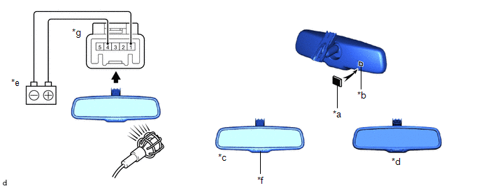
| *a | Black Colored Tape | *b | Forward Sensor |
| *c | Bright | *d | Dark |
| *e | Auxiliary Battery | *f | AUTO Switch |
| *g | Component without harness connected (Inner Rear View Mirror Assembly) | - | - |
(1) Connect a positive (+) lead from the auxiliary battery to terminal 4 (IG) and a negative (-) lead to terminal 1 (E).
(2) Press the AUTO switch.
(3) Attach black colored tape to the forward sensor to prevent it from sensing.
(4) Light up the mirror with an electric light, and check that the mirror surface changes from bright to dark.
OK:
Mirror surface changes from bright to dark.
If the result is not as specified, replace the inner rear view mirror assembly.
 Problem Symptoms Table
PROBLEM SYMPTOMS TABLE HINT: Use the table below to help determine the cause of problem symptoms. If multiple suspected areas are listed, the potential causes of the symptoms are listed in order of probability in the "Suspected Area" column of the table...
 Removal
REMOVAL PROCEDURE 1. REMOVE INNER REAR VIEW MIRROR STAY HOLDER COVER (w/o Pre-collision System) (a) Slide the inner rear view mirror stay holder cover to disengage the guides as shown in the illustration...
Other information:
Toyota Yaris XP210 (2020-2026) Reapir and Service Manual: ECU Internal Error (P164400)
DESCRIPTION If a malfunction is detected in the starter circuit, the engine stop and start ECU stores DTC P164400 and blinks the stop and start cancel indicator. DTC No. Detection Item DTC Detection Condition Trouble Area Warning Indicate Memory Note P164400 ECU Internal Error Both of the following conditions are met for 0...
Toyota Yaris XP210 (2020-2026) Reapir and Service Manual: How To Proceed With Troubleshooting
CAUTION / NOTICE / HINT HINT: Use these procedures to troubleshoot the power integration system. *: Use the GTS. PROCEDURE 1. VEHICLE BROUGHT TO WORKSHOP NEXT 2. INSPECT AUXILIARY BATTERY VOLTAGE (a) Measure the auxiliary battery voltage with the ignition switch off...
Categories
- Manuals Home
- Toyota Yaris Owners Manual
- Toyota Yaris Service Manual
- Maintenance
- Power Integration No.1 System Missing Message (B235287,B235587,B235787-B235987)
- Engine & Hybrid System
- New on site
- Most important about car
Front Seat Belt Pretensioners
The front seat belt pretensioners are designed to deploy in moderate or severe frontal, near frontal collisions.
In addition, the pretensioners operate when a side collision or a rollover accident is detected. The pretensioners operate differently depending on what types of air bags are equipped. For more details about the seat belt pretensioner operation, refer to the SRS Air Bag Deployment Criteria.