Toyota Yaris: Automatic High Beam Main Switch / Inspection
INSPECTION
PROCEDURE
1. INSPECT AUTO HIGH BEAM SWITCH
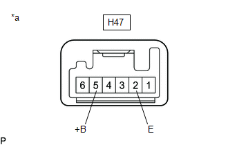
(a) Check the resistance.
| (1) Measure the resistance according to the value(s) in the table below. Standard Resistance:
If the result is not as specified, replace the auto high beam switch. |
|
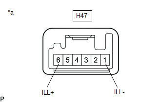
(b) Check the illumination.
| (1) Apply auxiliary battery voltage to the auto high beam switch and check that the switch illuminates. OK:
If the result is not as specified, replace the auto high beam switch. |
|
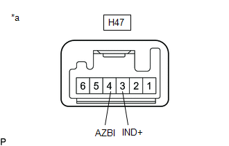
| (2) Apply auxiliary battery voltage to the auto high beam switch and check that the switch indicator illuminates. OK:
If the result is not as specified, replace the auto high beam switch. |
|
 Removal
REMOVAL PROCEDURE 1. REMOVE CENTER LOWER INSTRUMENT COVER Click here
2. REMOVE LOWER INSTRUMENT PANEL FINISH PANEL Click here
3. REMOVE SWITCH HOLE BASE SUB-ASSEMBLY Click here
4...
 Installation
INSTALLATION PROCEDURE 1. INSTALL AUTO HIGH BEAM SWITCH (a) Engage the claws to install the auto high beam switch as shown in the illustration.
2...
Other information:
Toyota Yaris XP210 (2020-2026) Reapir and Service Manual: Installation
INSTALLATION CAUTION / NOTICE / HINT HINT: Use the same procedure for the RH side and LH side. The following procedure is for the LH side. PROCEDURE 1. TEMPORARILY INSTALL REAR NO. 1 SUSPENSION ARM ASSEMBLY (a) Temporarily install the rear No...
Toyota Yaris XP210 (2020-2026) Reapir and Service Manual: Inspection
INSPECTION PROCEDURE 1. INSPECT STEERING PAD SWITCH ASSEMBLY (w/ Dynamic Radar Cruise Control System) (a) Check the resistance. (1) Measure the resistance according to the value(s) in the table below. *a Component without harness connected (Steering Pad Switch Assembly) *b Up *c Down *d Right *e Left *f OK *g Back *h On/off Hook *i Voice *j Volume+ *k Volume- *l Seek+ *m Seek- *n MODE *o +RES *p -SET *q CANCEL *r Lane Tracing Assist *s Distance Control *t Cruise Control Main Standard Resistance: Tester Connection Condition Specified Condition 3 (AU1) - 10 (EAU) No switch pushed 95 to 105 kΩ 3 (AU1) - 10 (EAU) Seek+ switch pushed Below 2...
Categories
- Manuals Home
- Toyota Yaris Owners Manual
- Toyota Yaris Service Manual
- Adjustment
- Engine & Hybrid System
- Maintenance
- New on site
- Most important about car
Turning the Engine Off
Stop the vehicle completely. Manual transaxle: Shift into neutral and set the parking brake.Automatic transaxle: Shift the selector lever to the P position and set the parking brake.
Press the push button start to turn off the engine. The ignition position is off.