Toyota Yaris: Engine Coolant Temperature Sensor / Inspection
INSPECTION
PROCEDURE
1. INSPECT ENGINE COOLANT TEMPERATURE SENSOR
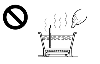
CAUTION:
- Do not put your hands into the water that has been heated for the inspection.
- Touching the heated water could result in burns.
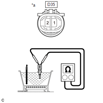
| (a) Measure the resistance according to the value(s) in the table below. Standard Resistance:
NOTICE: If checking the engine coolant temperature sensor in water, be careful not to allow water to contact the terminals. After checking, wipe the water off the engine coolant temperature sensor. If the result is not as specified, replace the engine coolant temperature sensor. |
|
 Components
C..
 Removal
REMOVAL CAUTION / NOTICE / HINT The necessary procedures (adjustment, calibration, initialization or registration) that must be performed after parts are removed and installed, or replaced during radiator assembly removal/installation are shown below...
Other information:
Toyota Yaris XP210 (2020-2026) Reapir and Service Manual: Brake System Control Module "A" System Voltage System Voltage Low (C137BA2)
DESCRIPTION If a malfunction is detected in the power supply circuit, the skid control ECU (brake actuator assembly) stores this DTC and the fail-safe function prohibits ABS operation. This DTC is stored when the +BS terminal voltage meets one of the DTC detection conditions due to a malfunction in the power supply or charging circuit such as the auxiliary battery or alternator circuit, etc...
Toyota Yaris XP210 (2020-2026) Reapir and Service Manual: Dtc Check / Clear
DTC CHECK / CLEAR CHECK DTC (a) Check for DTCs (Test Failed / Pending / Confirmed). Body Electrical > Pre-Collision System > Trouble Codes GTS Display Description Test Failed Represent malfunctions that were detected during the current trip...
Categories
- Manuals Home
- Toyota Yaris Owners Manual
- Toyota Yaris Service Manual
- Power Integration No.1 System Missing Message (B235287,B235587,B235787-B235987)
- How to connect USB port/Auxiliary jack
- Maintenance
- New on site
- Most important about car
Supplemental Restraint System (SRS) Precautions
The front and side supplemental restraint systems (SRS) include different types of air bags. Please verify the different types of air bags which are equipped on your vehicle by locating the “SRS AIRBAG” location indicators. These indicators are visible in the area where the air bags are installed.
The air bags are installed in the following locations:
The steering wheel hub (driver air bag) The front passenger dashboard (front passenger air bag) The outboard sides of the front seatbacks (side air bags) The front and rear window pillars, and the roof edge along both sides (curtain air bags)