
Toyota Yaris: AUX/USB mode / How to use AUX mode
Toyota Yaris XP210 (2020-2026) Owner's Manual / Interior Features / Audio System / AUX/USB mode / How to use AUX mode
Select the  icon on the home
screen and display the Entertainment screen.
icon on the home
screen and display the Entertainment screen.
Select  to switch to the AUX
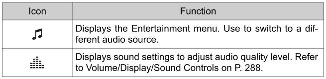
mode. The following icons are displayed in the lower part of the center display.
to switch to the AUX
mode. The following icons are displayed in the lower part of the center display.
If a device is not connected to the auxiliary jack, the mode does not switch to the AUX mode.
Adjust the audio volume using the portable audio device, commander switch, or audio control switch.
Audio adjustments can also be made using the portable audio device’s volume setting.
If the connection plug is pulled out from the auxiliary jack while in AUX mode, noise may occur.
 How to connect USB port/Auxiliary jack
USB port
Auxiliary jack
Connecting a device
Connect the connector on the device to the USB port.
Connecting with a connector cable
Connect the device plug/connector cable to the auxiliary jack/USB
port...
 How to use USB mode
This unit does not support a USB 3.0 device. In addition, other
devices may not be supported depending on the model or OS version.
USB devices formatted to FAT32 are supported (USB devices formatted to other
formats such as NTFS are not supported)...
Other information:
Toyota Yaris XP210 (2020-2026) Reapir and Service Manual: Headlight LH Circuit (B243900,B243A00)
DESCRIPTION The light control LED ECU supplies internally boosted voltage to the light control LED ECU LH so that the current supplied to the LED is always maintained at a constant value. These DTCs are also output when the main body ECU (multiplex network body ECU) detects malfunctions while monitoring the applied voltage...
Toyota Yaris XP210 (2020-2026) Reapir and Service Manual: Side Turn Signal Light Assembly
ComponentsCOMPONENTS ILLUSTRATION *1 OUTER MIRROR LOWER COVER *2 SIDE TURN SIGNAL LIGHT ASSEMBLY RemovalREMOVAL CAUTION / NOTICE / HINT HINT: Use the same procedure for the RH and LH sides. The procedure listed below is for the LH side...
Categories
- Manuals Home
- Toyota Yaris Owners Manual
- Toyota Yaris Service Manual
- To Set Speed
- Removal
- G16e-gts (engine Mechanical)
- New on site
- Most important about car
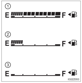
Fuel Gauge
The fuel gauge shows approximately how much fuel is remaining in the tank when the ignition is switched ON. We recommend keeping the tank over 1/4 full.

Copyright © 2026 www.toyaris4.com