Toyota Yaris: Theft Deterrent System / Horn Circuit
DESCRIPTION
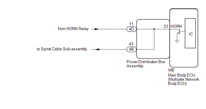
When the theft deterrent system is switched from the armed state to the alarm sounding state, the main body ECU (multiplex network body ECU) transmits a signal to cause the horn to sound at intervals of 0.4 seconds.
WIRING DIAGRAM
CAUTION / NOTICE / HINT
NOTICE:
If the main body ECU (multiplex network body ECU) is replaced, refer to the Registration.
Click here

PROCEDURE
| 1. | CHECK HORNS OPERATION |
(a) Press the horn switch and check if the horns sound.
| Result | Proceed to |
|---|---|
| Horns sound | A |
| Horns do not sound | B |
| B |
 | GO TO HORN SYSTEM |
|

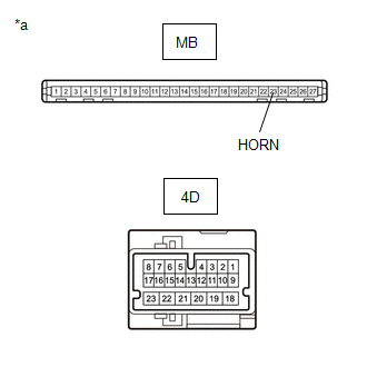
| 2. | CHECK HARNESS AND CONNECTOR (POWER DISTRIBUTION BOX ASSEMBLY - AUXILIARY BATTERY) |
(a) Disconnect the 4D power distribution box assembly connector.
(b) Measure the voltage according to the value(s) in the table below.
Standard Voltage:
| Tester Connection | Switch Condition | Specified Condition |
|---|---|---|
| 4D-11 - Body ground | Ignition switch off | 11 to 14 V |
| NG |
 | REPAIR OR REPLACE HARNESS OR CONNECTOR |
|

| 3. | INSPECT POWER DISTRIBUTION BOX ASSEMBLY |
(a) Remove the power distribution box assembly.
Click here

| (b) Measure the resistance according to the value(s) in the table below. Standard Resistance:
|
|
| OK |
 | REPLACE MAIN BODY ECU (MULTIPLEX NETWORK BODY ECU) |
| NG |
 | REPLACE POWER DISTRIBUTION BOX ASSEMBLY |