Toyota Yaris: Sfi System / High Pressure Fuel Pump Circuit Open (P123513)
DESCRIPTION
The high-pressure direct injection fuel system consists of a spill control valve, check valve, fuel relief valve, fuel pressure sensor (for high pressure side), fuel pump assembly (for high pressure side) and direct fuel injector assemblies. The spill control valve adjusts the return volume of the high-pressure fuel. The check valve mechanically opens and closes the paths to the fuel delivery pipes. The relief valve releases the fuel back to the fuel tank if the high-pressure fuel system malfunctions. The fuel pump assembly (for high pressure side) is installed to the cylinder head cover and operated by a cam installed to the end of the exhaust camshaft. Rotation of the camshaft moves the pump plunger inside the fuel pump assembly (for high pressure side) up and down, pressurizing the fuel. The pressurized fuel opens the check valve and is pumped into the fuel delivery pipe.
| DTC No. | Detection Item | DTC Detection Condition | Trouble Area | MIL | Note |
|---|---|---|---|---|---|
| P123513 | High Pressure Fuel Pump Circuit Open | Open or short in fuel pump assembly (for high pressure side of bank 1) circuit detected 60 times or more (1 trip detection logic). |
| Comes on | SAE: P1235 |
MONITOR DESCRIPTION
If an open or short in the fuel pump assembly (for high pressure side) circuit is detected after the engine is started, the ECM will illuminate the MIL and store this DTC.
MONITOR STRATEGY
| Required Sensors/Components (Main) | Fuel pump assembly (for high pressure side) |
| Required Sensors/Components (Related) | Injector driver (ECM) |
| Frequency of Operation | Continuous |
CONFIRMATION DRIVING PATTERN
- Connect the GTS to the DLC3.
- Turn the ignition switch to ON.
- Turn the GTS on.
- Clear the DTCs (even if no DTCs are stored, perform the clear DTC procedure).
- Turn the ignition switch off and wait for at least 30 seconds.
- Start the engine [A].
- Idle the engine for 10 seconds [B].
- Turn the GTS on.
- Enter the following menus: Powertrain / Engine / Trouble Codes [C].
-
Read the pending DTCs.
HINT:
- If a pending DTC is output, the system is malfunctioning.
- If a pending DTC is not output, perform the following procedure.
- Enter the following menus: Powertrain / Engine / Utility / All Readiness.
- Input the DTC: P123513.
-
Check the DTC judgment result.
GTS Display
Description
NORMAL
- DTC judgment completed
- System normal
ABNORMAL
- DTC judgment completed
- System abnormal
INCOMPLETE
- DTC judgment not completed
- Perform driving pattern after confirming DTC enabling conditions
HINT:
- If the judgment result is NORMAL, the system is normal.
- If the judgment result is ABNORMAL, the system has a malfunction.
- If the judgment result is INCOMPLETE, perform steps [B] through [C] again.
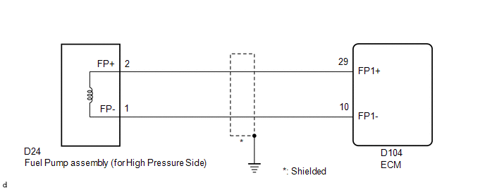
WIRING DIAGRAM
CAUTION / NOTICE / HINT
HINT:
- If the current from the EDU relay is cut because DTC P062D13 is stored, DTC P123513 will be stored even if the fuel pump assembly (for high pressure side) is normal.
- Read Freeze Frame Data using the GTS. The ECM records vehicle and driving condition information as Freeze Frame Data the moment a DTC is stored. When troubleshooting, Freeze Frame Data can help determine if the vehicle was moving or stationary, if the engine was warmed up or not, if the air fuel ratio was lean or rich, and other data from the time the malfunction occurred.
PROCEDURE
| 1. | INSPECT FUEL PUMP ASSEMBLY (FOR HIGH PRESSURE SIDE) |
Click here

HINT:
Perform "Inspection After Repair" after replacing the fuel pump assembly (for high pressure side).
Click here

| NG |
 | REPLACE FUEL PUMP ASSEMBLY (FOR HIGH PRESSURE SIDE) |
|

| 2. | CHECK HARNESS AND CONNECTOR (FUEL PUMP ASSEMBLY (FOR HIGH PRESSURE SIDE) - ECM) |
(a) Disconnect the ECM connector.
(b) Disconnect the fuel pump assembly (for high pressure side) connector.
(c) Measure the resistance according to the value(s) in the table below.
Standard Resistance:
| Tester Connection | Condition | Specified Condition |
|---|---|---|
| D24-2(FP+) - D104-29(FP1+) | Always | Below 1 Ω |
| D24-1(FP-) - D104-10(FP1-) | Always | Below 1 Ω |
| D24-2(FP+) or D104-29(FP1+) - Body ground and other terminals | Always | 10 kΩ or higher |
| D24-1(FP-) or D104-10(FP1-) - Body ground and other terminals | Always | 10 kΩ or higher |
| OK |
 | REPLACE ECM |
| NG |
 | REPAIR OR REPLACE HARNESS OR CONNECTOR |
 Charge Air Cooler Temperature Sensor 2 Bank 1 Circuit Short to Battery or Open (P10D315)
DESCRIPTION Refer to DTC P10D311. Click here
DTC No. Detection Item DTC Detection Condition Trouble Area MIL Note P10D315 Charge Air Cooler Temperature Sensor 2 Bank 1 Circuit Short to Battery or Open The output voltage from the intake air temperature sensor is higher than 4...
 Fuel Pump Control (All Phase) Circuit Open (P12D013-P12D313)
DESCRIPTION Refer to DTC P062712. Click here
DTC No. Detection Item DTC Detection Condition Trouble Area MIL Note P12D013 Fuel Pump Control (All Phase) Circuit Open When the fuel pump control ECU operation duty ratio is 3 to 65%, an open is detected in the FPU, FPV and FPW circuit for 3 seconds or more (1 trip detection logic)...
Other information:
Toyota Yaris XP210 (2020-2026) Reapir and Service Manual: Data List / Active Test
DATA LIST / ACTIVE TEST DATA LIST NOTICE: In the table below, the values listed under "Normal Condition" are reference values. Do not depend solely on these reference values when deciding whether a part is faulty or not. HINT: Using the GTS to read the Data List allows the values or states of switches, sensors, actuators and other items to be read without removing any parts...
Toyota Yaris XP210 (2020-2026) Owner's Manual: Hood
With the vehicle parked, pull the release handle to unlock the hood. Insert your hand into the hood opening, slide the latch lever to the right, and lift up the hood. Grasp the support rod in the padded area and secure it in the support rod hole indicated by the arrow to hold the hood open...
Categories
- Manuals Home
- Toyota Yaris Owners Manual
- Toyota Yaris Service Manual
- To Set Speed
- Diagnostic Trouble Code Chart
- Adjustment
- New on site
- Most important about car
Front Seat Belt Pretensioners
The front seat belt pretensioners are designed to deploy in moderate or severe frontal, near frontal collisions.
In addition, the pretensioners operate when a side collision or a rollover accident is detected. The pretensioners operate differently depending on what types of air bags are equipped. For more details about the seat belt pretensioner operation, refer to the SRS Air Bag Deployment Criteria.