Toyota Yaris: Sfi System / Charge Air Cooler Temperature Sensor 2 Bank 1 Circuit Short to Battery or Open (P10D315)
DESCRIPTION
Refer to DTC P10D311.
Click here

| DTC No. | Detection Item | DTC Detection Condition | Trouble Area | MIL | Note |
|---|---|---|---|---|---|
| P10D315 | Charge Air Cooler Temperature Sensor 2 Bank 1 Circuit Short to Battery or Open | The output voltage from the intake air temperature sensor is higher than 4.9 V for 3 seconds or more (1 trip detection logic). |
| - | SAE: P10D6 |
HINT:
When a DTC is output, check the Data List item "Intake Air Temperature B1S2 (Turbo)" using the GTS.
Click here

| DTC No. | Intake Air Temperature B1S2 (Turbo) | Malfunction |
|---|---|---|
| P10D315 | -40°C (-40°F) |
|
If the Data List displays a normal value, the normal value may be due to a temporary recovery from the malfunction condition. Check for intermittent problems.
MONITOR DESCRIPTION
The ECM calculates the intake manifold internal temperature from the intake air temperature sensor output voltage. If the intake air temperature sensor output voltage is outside the normal range, there may be a malfunction or open or short circuit in the intake air temperature sensor. In this case, the ECM stores a DTC.
Example:
If the sensor output voltage is higher than 4.9 V for 3 seconds or more, the ECM stores DTC P10D315.
CONFIRMATION DRIVING PATTERN
- Connect the GTS to the DLC3.
- Turn the ignition switch to ON and turn the GTS on.
- Clear the DTCs (even if no DTCs are stored, perform the clear DTC procedure).
- Turn the ignition switch off and wait for at least 30 seconds.
- Turn the ignition switch to ON and turn the GTS on.
- Wait 5 seconds or more.
- Enter the following menus: Powertrain / Engine / Trouble Codes.
-
Read the pending DTCs.
HINT:
- If a pending DTC is output, the system is malfunctioning.
- If a pending DTC is not output, perform the following procedure.
- Enter the following menus: Powertrain / Engine / Utility / All Readiness.
- Input the DTC: P10D315.
-
Check the DTC judgment result.
GTS Display
Description
NORMAL
- DTC judgment completed
- System normal
ABNORMAL
- DTC judgment completed
- System abnormal
INCOMPLETE
- DTC judgment not completed
- Perform driving pattern after confirming DTC enabling conditions
HINT:
- If the judgment result shows NORMAL, the system is normal.
- If the judgment result shows ABNORMAL, the system has a malfunction.
WIRING DIAGRAM
Refer to DTC P10D311.
Click here

CAUTION / NOTICE / HINT
HINT:
Read Freeze Frame Data using the GTS. The ECM records vehicle and driving condition information as Freeze Frame Data the moment a DTC is stored. When troubleshooting, Freeze Frame Data can help determine if the vehicle was moving or stationary, if the engine was warmed up or not, if the air fuel ratio was lean or rich, and other data from the time the malfunction occurred.
PROCEDURE
| 1. | READ VALUE USING GTS (CHECK FOR OPEN IN WIRE HARNESS) |
| (a) Disconnect the No. 1 turbo pressure sensor connector. |
|
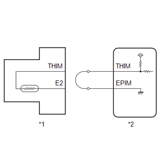
(b) Connect terminals 4 (THIM) and 2 (E2) of the No. 1 turbo pressure sensor connector on the wire harness side.
(c) Enter the following menus.
Powertrain > Engine > Data List| Tester Display |
|---|
| Intake Air Temperature B1S2 (Turbo) |
(d) Read the value displayed on the GTS.
Standard value:
140°C (284°F)
| OK |
 | REPLACE NO. 1 TURBO PRESSURE SENSOR |
|

| 2. | CHECK HARNESS AND CONNECTOR (NO. 1 TURBO PRESSURE SENSOR - ECM) |
(a) Disconnect the No. 1 turbo pressure sensor connector.
(b) Disconnect the ECM connector.
(c) Measure the resistance according to the value(s) in the table below.
Standard Resistance:
| Tester Connection | Condition | Specified Condition |
|---|---|---|
| D95-4(THIM) - D104-99(THIM) | Always | Below 1 Ω |
| D95-2(E2) - D104-76(EPIM) | Always | Below 1 Ω |
| D95-4(THIM) or D104-99(THIM) - Other terminals | Always | 10 kΩ or higher |
| OK |
 | REPLACE ECM |
| NG |
 | REPAIR OR REPLACE HARNESS OR CONNECTOR |
 Charge Air Cooler Temperature Sensor 2 Bank 1 Circuit Short to Ground (P10D311)
DESCRIPTION
The intake air temperature sensor, built into the No. 1 turbo pressure sensor, monitors the intake air temperature. The intake air temperature sensor has a built-in thermistor with a resistance that varies according to the temperature of the intake air...
 High Pressure Fuel Pump Circuit Open (P123513)
DESCRIPTION The high-pressure direct injection fuel system consists of a spill control valve, check valve, fuel relief valve, fuel pressure sensor (for high pressure side), fuel pump assembly (for high pressure side) and direct fuel injector assemblies...
Other information:
Toyota Yaris XP210 (2020-2025) Reapir and Service Manual: Problem Symptoms Table
PROBLEM SYMPTOMS TABLE HINT: Use the table below to help determine the cause of problem symptoms. If multiple suspected areas are listed, the potential causes of the symptoms are listed in order of probability in the "Suspected Area" column of the table...
Toyota Yaris XP210 (2020-2025) Reapir and Service Manual: System Description
SYSTEM DESCRIPTION STOP AND START CONTROL The stop and start system operates according to the following conditions, achieving appropriate engine stop and start control together with safe and smooth driving characteristics. (a) When all of the conditions in the following table have been met, the engine is stopped by stop and start control...
Categories
- Manuals Home
- Toyota Yaris Owners Manual
- Toyota Yaris Service Manual
- How to connect USB port/Auxiliary jack
- Maintenance
- Headlights
- New on site
- Most important about car
Turning the Engine Off
Stop the vehicle completely. Manual transaxle: Shift into neutral and set the parking brake.Automatic transaxle: Shift the selector lever to the P position and set the parking brake.
Press the push button start to turn off the engine. The ignition position is off.