Toyota Yaris: Sfi System / Charge Air Cooler Temperature Sensor 2 Bank 1 Circuit Short to Ground (P10D311)
DESCRIPTION
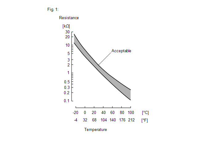
The intake air temperature sensor, built into the No. 1 turbo pressure sensor, monitors the intake air temperature. The intake air temperature sensor has a built-in thermistor with a resistance that varies according to the temperature of the intake air. When the intake air temperature is low, the resistance of the thermistor increases. When the temperature is high, the resistance drops. These variations in resistance are transmitted to the ECM as voltage changes (See Fig. 1).
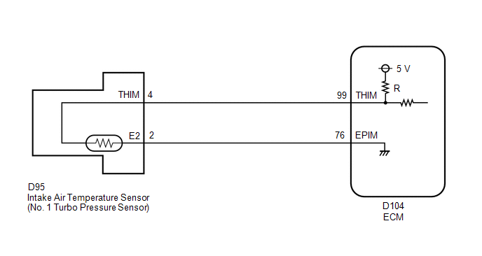
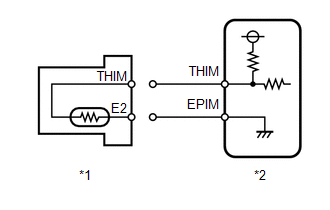
The intake air temperature sensor is powered by a 5 V supply from the THIM terminal of the ECM, via resistor R.
Resistor R and the intake air temperature sensor are connected in series. When the resistance value of the intake air temperature sensor changes, according to changes in the intake air temperature, the voltage at terminal THIM also varies. Based on this signal, the ECM increases the fuel injection volume when the engine is cold to improve driveability.
HINT:
When DTC P10D311 or P10D315 is stored, the ECM enters fail-safe mode. During fail-safe mode, the intake air temperature is estimated to be 45°C (113°F) by the ECM. Fail-safe mode continues until a pass condition is detected.
| DTC No. | Detection Item | DTC Detection Condition | Trouble Area | MIL | Note |
|---|---|---|---|---|---|
| P10D311 | Charge Air Cooler Temperature Sensor 2 Bank 1 Circuit Short to Ground | The output voltage from the intake air temperature sensor is 0.1 V or less for 3 seconds or more (1 trip detection logic). |
| - | SAE: P10D5 |
HINT:
When a DTC is output, check the Data List item "Intake Air Temperature B1S2 (Turbo)" using the GTS.
Click here

| DTC No. | Intake Air Temperature B1S2 (Turbo) | Malfunction |
|---|---|---|
| P10D311 | 140°C (284°F) | Short in THIM circuit to ground |
If the Data List displays a normal value, the normal value may be due to a temporary recovery from the malfunction condition. Check for intermittent problems.
MONITOR DESCRIPTION
The ECM calculates the intake manifold internal temperature from the intake air temperature sensor output voltage. If the intake air temperature sensor output voltage is outside the normal range, there may be a malfunction or open or short circuit in the intake air temperature sensor. In this case, the ECM stores a DTC.
Example:
When the sensor output voltage is 0.1 V or less for 3 seconds or more, the ECM stores DTC P10D311.
CONFIRMATION DRIVING PATTERN
- Connect the GTS to the DLC3.
- Turn the ignition switch to ON and turn the GTS on.
- Clear the DTCs (even if no DTCs are stored, perform the clear DTC procedure).
- Turn the ignition switch off and wait for at least 30 seconds.
- Turn the ignition switch to ON and turn the GTS on.
- Wait 5 seconds or more.
- Enter the following menus: Powertrain / Engine / Trouble Codes.
-
Read the pending DTCs.
HINT:
- If a pending DTC is output, the system is malfunctioning.
- If a pending DTC is not output, perform the following procedure.
- Enter the following menus: Powertrain / Engine / Utility / All Readiness.
- Input the DTC: P10D311.
-
Check the DTC judgment result.
GTS Display
Description
NORMAL
- DTC judgment completed
- System normal
ABNORMAL
- DTC judgment completed
- System abnormal
INCOMPLETE
- DTC judgment not completed
- Perform driving pattern after confirming DTC enabling conditions
HINT:
- If the judgment result shows NORMAL, the system is normal.
- If the judgment result shows ABNORMAL, the system has a malfunction.
WIRING DIAGRAM
CAUTION / NOTICE / HINT
HINT:
Read Freeze Frame Data using the GTS. The ECM records vehicle and driving condition information as Freeze Frame Data the moment a DTC is stored. When troubleshooting, Freeze Frame Data can help determine if the vehicle was moving or stationary, if the engine was warmed up or not, if the air fuel ratio was lean or rich, and other data from the time the malfunction occurred.
PROCEDURE
| 1. | READ VALUE USING GTS (CHECK FOR SHORT IN WIRE HARNESS) |
| (a) Disconnect the No. 1 turbo pressure sensor connector. |
|
(b) Enter the following menus.
Powertrain > Engine > Data List| Tester Display |
|---|
| Intake Air Temperature B1S2 (Turbo) |
(c) Read the value displayed on the GTS.
Standard value:
-40°C (-40°F)
| OK |
 | REPLACE NO. 1 TURBO PRESSURE SENSOR |
|

| 2. | CHECK HARNESS AND CONNECTOR (NO. 1 TURBO PRESSURE SENSOR - ECM) |
(a) Disconnect the No. 1 turbo pressure sensor connector.
(b) Disconnect the ECM connector.
(c) Measure the resistance according to the value(s) in the table below.
Standard Resistance:
| Tester Connection | Condition | Specified Condition |
|---|---|---|
| D95-4(THIM) or D104-99(THIM) - Body ground and other terminals | Always | 10 kΩ or higher |
| OK |
 | REPLACE ECM |
| NG |
 | REPAIR OR REPLACE HARNESS OR CONNECTOR |
 Fuel Rail Pressure Sensor (Low) Circuit Short to Battery or Open (P107A15)
DESCRIPTION Refer to DTC P107A11. Click here
DTC No. Detection Item DTC Detection Condition Trouble Area MIL Note P107A15 Fuel Rail Pressure Sensor (Low) Circuit Short to Battery or Open The No...
 Charge Air Cooler Temperature Sensor 2 Bank 1 Circuit Short to Battery or Open (P10D315)
DESCRIPTION Refer to DTC P10D311. Click here
DTC No. Detection Item DTC Detection Condition Trouble Area MIL Note P10D315 Charge Air Cooler Temperature Sensor 2 Bank 1 Circuit Short to Battery or Open The output voltage from the intake air temperature sensor is higher than 4...
Other information:
Toyota Yaris XP210 (2020-2024) Reapir and Service Manual: Brake System
PrecautionPRECAUTION NOTICE: This vehicle is equipped with an SRS (Supplemental Restraint System). Failure to carry out service operations in the correct sequence could cause the SRS to unexpectedly deploy during servicing. This may cause a serious accident...
Toyota Yaris XP210 (2020-2024) Reapir and Service Manual: System Description
SYSTEM DESCRIPTION CXPI COMMUNICATION SYSTEM DESCRIPTION The multiplex communication system [CXPI] is used for communication systems between body system components. When communication fails due to an open circuit, etc. on the communication line, the function that outputs a DTC related to the circuit according to the control master ECU and the fail-safe function that maintains minimum performance and protects the system activate...
Categories
- Manuals Home
- Toyota Yaris Owners Manual
- Toyota Yaris Service Manual
- Key Battery Replacement
- Diagnostic Trouble Code Chart
- Operating the Radio
- New on site
- Most important about car
Supplemental Restraint System (SRS) Precautions
The front and side supplemental restraint systems (SRS) include different types of air bags. Please verify the different types of air bags which are equipped on your vehicle by locating the “SRS AIRBAG” location indicators. These indicators are visible in the area where the air bags are installed.
The air bags are installed in the following locations:
The steering wheel hub (driver air bag) The front passenger dashboard (front passenger air bag) The outboard sides of the front seatbacks (side air bags) The front and rear window pillars, and the roof edge along both sides (curtain air bags)