Toyota Yaris: Sfi System / Fuel Rail Pressure Sensor (Low) Circuit Short to Battery or Open (P107A15)
DESCRIPTION
Refer to DTC P107A11.
Click here

| DTC No. | Detection Item | DTC Detection Condition | Trouble Area | MIL | Note |
|---|---|---|---|---|---|
| P107A15 | Fuel Rail Pressure Sensor (Low) Circuit Short to Battery or Open | The No. 2 fuel pressure sensor (for low pressure side) output voltage is higher than 4.85 V for 3 seconds or more (1 trip detection logic). |
| Comes on | SAE: P107D |
HINT:
When a DTC is output, check the Data List item "Fuel Pressure (Low) / Fuel Pressure 2" using the GTS.
Click here

| DTC No. | Fuel Pressure (Low) / Fuel Pressure 2 | Malfunction |
|---|---|---|
| P107A15 | Approximately 750 kPag or higher |
|
If the Data List displays a normal value, the normal value may be due to a temporary recovery from the malfunction condition. Check for intermittent problems.
MONITOR DESCRIPTION
This DTC is stored if the No. 2 fuel pressure sensor (for low pressure side) output voltage is out of the standard range due to an open or short in the sensor circuit.
MONITOR STRATEGY
| Required Sensors/Components | No. 2 Fuel pressure sensor (for low pressure side) |
| Frequency of Operation | Continuous |
CONFIRMATION DRIVING PATTERN
- Connect the GTS to the DLC3.
- Turn the ignition switch to ON.
- Turn the GTS on.
- Clear the DTCs (even if no DTCs are stored, perform the clear DTC procedure).
- Turn the ignition switch off and wait for at least 30 seconds.
- Start the engine.
- Idle the engine for 10 seconds or more [A].
- Turn the GTS on.
- Enter the following menus: Powertrain / Engine / Trouble Codes [B].
-
Read the pending DTCs.
HINT:
- If a pending DTC is output, the system is malfunctioning.
- If a pending DTC is not output, perform the following procedure.
- Enter the following menus: Powertrain / Engine / Utility / All Readiness.
- Input the DTC: P107A15.
-
Check the DTC judgment result.
GTS Display
Description
NORMAL
- DTC judgment completed
- System normal
ABNORMAL
- DTC judgment completed
- System abnormal
INCOMPLETE
- DTC judgment not completed
- Perform driving pattern after confirming DTC enabling conditions
HINT:
- If the judgment result is NORMAL, the system is normal.
- If the judgment result is ABNORMAL, the system has a malfunction.
- If the judgment result is INCOMPLETE, perform steps [A] through [B] again.
WIRING DIAGRAM
Refer to DTC P107A11.
Click here

CAUTION / NOTICE / HINT
HINT:
Read Freeze Frame Data using the GTS. The ECM records vehicle and driving condition information as Freeze Frame Data the moment a DTC is stored. When troubleshooting, Freeze Frame Data can help determine if the vehicle was moving or stationary, if the engine was warmed up or not, if the air fuel ratio was lean or rich, and other data from the time the malfunction occurred.
PROCEDURE
| 1. | CHECK HARNESS AND CONNECTOR |
HINT:
Make sure that the connector is properly connected. If it is not, securely connect it and check for DTCs again.
(a) Disconnect the No. 2 fuel pressure sensor (for low pressure side) connector.
(b) Turn the ignition switch to ON.
| (c) Measure the voltage according to the value(s) in the table below. Standard Voltage:
|
|
(d) Turn the ignition switch off and wait for at least 30 seconds.
(e) Measure the resistance according to the value(s) in the table below.
Standard Resistance:
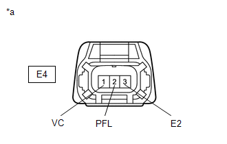
| Tester Connection | Condition | Specified Condition |
|---|---|---|
| E4-3(E2) - Body ground | Ignition switch off | Below 1 Ω |
| E4-1(VC) - E4-2(PFL) | Ignition switch off | 171 to 189 kΩ |
HINT:
Perform "Inspection After Repair" after replacing the No. 2 fuel pressure sensor (for low pressure side).
Click here

| OK |
 | REPLACE NO. 2 FUEL PRESSURE SENSOR (FOR LOW PRESSURE SIDE) |
|

| 2. | CHECK HARNESS AND CONNECTOR (NO. 2 FUEL PRESSURE SENSOR (FOR LOW PRESSURE SIDE) - ECM) |
(a) Disconnect the No. 2 fuel pressure sensor (for low pressure side) connector.
(b) Disconnect the ECM connector.
(c) Measure the resistance according to the value(s) in the table below.
Standard Resistance:
| Tester Connection | Condition | Specified Condition |
|---|---|---|
| E4-3(E2) - D104-119(EPFL) | Always | Below 1 Ω |
| E4-2(PFL) - D104-121(PFL) | Always | Below 1 Ω |
| E4-2(PFL) or D104-121(PFL) - Other terminals | Always | 10 kΩ or higher |
| OK |
 | REPLACE ECM |
| NG |
 | REPAIR OR REPLACE HARNESS OR CONNECTOR |
 Fuel Rail Pressure Sensor (Low) Circuit Short to Ground (P107A11)
DESCRIPTION
The No. 2 fuel pressure sensor (for low pressure side) replaces the fuel pressure with electrical signals and outputs them to the ECM. The ECM controls the optimal fuel pressure for the operation conditions to reduce the fuel pump power consumption and improve fuel economy...
 Charge Air Cooler Temperature Sensor 2 Bank 1 Circuit Short to Ground (P10D311)
DESCRIPTION
The intake air temperature sensor, built into the No. 1 turbo pressure sensor, monitors the intake air temperature. The intake air temperature sensor has a built-in thermistor with a resistance that varies according to the temperature of the intake air...
Other information:
Toyota Yaris XP210 (2020-2025) Reapir and Service Manual: Stop and Start Cancel Switch Circuit
DESCRIPTION Stop and start control can be disabled by pressing the stop and start system cancel switch (combination switch assembly). The stop and start system cancel switch (combination switch assembly) is a momentary-type switch that switches between on and off when the switch is pressed...
Toyota Yaris XP210 (2020-2025) Reapir and Service Manual: Components
COMPONENTS ILLUSTRATION *A for Driver Side *B for Front Passenger Side *1 FRONT SEAT VERTICAL ADJUSTER HANDLE *2 NO.1 RECLINING HINGE COVER *3 RECLINING ADJUSTER RELEASE HANDLE *4 SEAT ADJUSTER COVER CAP *5 FRONT SEAT CUSHION SHIELD *6 FRONT SEAT INNER CUSHION SHIELD ILLUSTRATION *1 SEPARATE TYPE FRONT SEATBACK ASSEMBLY - - Tightening torque for "Major areas involving basic vehicle performance such as moving/turning/stopping" : N*m (kgf*cm, ft...
Categories
- Manuals Home
- Toyota Yaris Owners Manual
- Toyota Yaris Service Manual
- Key Battery Replacement
- Opening and Closing the Liftgate/Trunk Lid
- Adjustment
- New on site
- Most important about car
Break-In Period
No special break-in is necessary, but a few precautions in the first 600 miles (1,000 km) may add to the performance, economy, and life of the vehicle.
Do not race the engine. Do not maintain one constant speed, either slow or fast, for a long period of time. Do not drive constantly at full-throttle or high engine rpm for extended periods of time. Avoid unnecessary hard stops. Avoid full-throttle starts.