Toyota Yaris: Sfi System / Fuel Pump Control (All Phase) Circuit Open (P12D013-P12D313)
DESCRIPTION
Refer to DTC P062712.
Click here

| DTC No. | Detection Item | DTC Detection Condition | Trouble Area | MIL | Note |
|---|---|---|---|---|---|
| P12D013 | Fuel Pump Control (All Phase) Circuit Open | When the fuel pump control ECU operation duty ratio is 3 to 65%, an open is detected in the FPU, FPV and FPW circuit for 3 seconds or more (1 trip detection logic). |
| - | SAE: P12D0 |
| P12D113 | Fuel Pump Control (U Phase) Circuit Open | When the fuel pump control ECU operation duty ratio is 3 to 65%, an open is detected in the FPU circuit for 3 seconds or more (1 trip detection logic). |
| - | SAE: P12D1 |
| P12D213 | Fuel Pump Control (V Phase) Circuit Open | When the fuel pump control ECU operation duty ratio is 3 to 65%, an open is detected in the FPV circuit for 3 seconds or more (1 trip detection logic). |
| - | SAE: P12D2 |
| P12D313 | Fuel Pump Control (W Phase) Circuit Open | When the fuel pump control ECU operation duty ratio is 3 to 65%, an open is detected in the FPW circuit for 3 seconds or more (1 trip detection logic). |
| - | SAE: P12D3 |
| DTC No. | Data List |
|---|---|
| P12D013 P12D113 P12D213 P12D313 | Fuel Pump Control Duty Ratio |
MONITOR DESCRIPTION
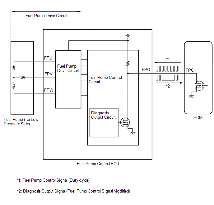
The fuel pump control ECU monitors the fuel pump drive circuit.
When a malfunction is detected in the fuel pump drive circuit, the diagnosis output circuit in the fuel pump control ECU modifies the operation signal sent by the ECM to indicate that there is a malfunction.
When the fuel pump control ECU operation duty ratio is 3 to 65% and the FPU, FPV or FPW terminal voltage is less than a certain value for 3 seconds or more, the diagnosis output circuit in the fuel pump control ECU modifies the operation signal sent by the ECM to indicate that there is a malfunction, and the ECM stores a DTC.
MONITOR STRATEGY
| Required Sensors/Components | Fuel pump control ECU |
| Frequency of Operation | Continuous |
CONFIRMATION DRIVING PATTERN
- Connect the GTS to the DLC3.
- Turn the ignition switch to ON.
- Turn the GTS on.
- Clear the DTCs (even if no DTCs are stored, perform the clear DTC procedure).
- Turn the ignition switch off and wait for at least 30 seconds.
- Turn the ignition switch to ON.
- Turn the GTS on.
- Start the engine and wait 10 seconds or more.
- Enter the following menus: Powertrain / Engine / Trouble Codes.
-
Read the pending DTCs.
HINT:
- If a pending DTC is output, the system is malfunctioning.
- If a pending DTC is not output, perform the following procedure.
- Enter the following menus: Powertrain / Engine / Utility / All Readiness.
- Input the DTC: P12D013, P12D113, P12D213 or P12D313.
-
Check the DTC judgment result.
GTS Display
Description
NORMAL
- DTC judgment completed
- System normal
ABNORMAL
- DTC judgment completed
- System abnormal
INCOMPLETE
- DTC judgment not completed
- Perform driving pattern after confirming DTC enabling conditions
HINT:
- If the judgment result is NORMAL, the system is normal.
- If the judgment result is ABNORMAL, the system is malfunctioning.
- If the judgment result is INCOMPLETE, run the engine at an engine speed of 2500 rpm or more for 10 seconds or more and check the DTC judgment result again.
WIRING DIAGRAM
Refer to DTC P062712.
Click here

CAUTION / NOTICE / HINT
HINT:
Read Freeze Frame Data using the GTS. The ECM records vehicle and driving condition information as Freeze Frame Data the moment a DTC is stored. When troubleshooting, Freeze Frame Data can help determine if the vehicle was moving or stationary, if the engine was warmed up or not, if the air fuel ratio was lean or rich, and other data from the time the malfunction occurred.
PROCEDURE
| 1. | PERFORM ACTIVE TEST USING GTS (FUEL PUMP SINGLE PHASE ENERGIZATION) |
HINT:
Make sure that the connector is properly connected. If it is not, securely connect it and check for DTCs again.
(a) Disconnect the fuel pump control ECU connector.
(b) Operate the fuel pump control ECU using the Active Test function and measure the voltage according to the value(s) in the table below.
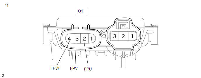
| *1 | Fuel Pump Control ECU | - | - |
| Tester Display |
|---|
| Fuel Pump Single Phase Energization |
Standard Voltage:
| Tester Connection | GTS Operation | Specified Condition |
|---|---|---|
| O1-2 (FPU) - Body ground | U Phase | 4.4 to 8.4 V* |
| O1-3 (FPV) - Body ground | V Phase | 4.4 to 8.4 V* |
| O1-4 (FPW) - Body ground | W Phase | 4.4 to 8.4 V* |
HINT:
- *: This Active Test limits the fuel pump control ECU output duty cycle to 50%. Therefore, the output voltage of the fuel pump control ECU will be approximately 50% of the power source voltage (+B terminal).
- Before performing this inspection, check that the auxiliary battery voltage is between 11 and 14 V (not depleted).
| NG |
 | REPLACE FUEL PUMP CONTROL ECU |
|

| 2. | CHECK HARNESS AND CONNECTOR (FUEL PUMP CONTROL ECU - FUEL PUMP (FOR LOW PRESSURE SIDE)) |
HINT:
Make sure that the connector is properly connected. If it is not, securely connect it and check for DTCs again.
(a) Disconnect the fuel pump control ECU connector.
(b) Disconnect the fuel pump (for low pressure side) connector.
(c) Measure the resistance according to the value(s) in the table below.
Standard Resistance:
| Tester Connection | Condition | Specified Condition |
|---|---|---|
| O1-2 (FPU) - O21-3 (BLPU) | Always | Below 1 Ω |
| O1-3 (FPV) - O21-4 (BLPV) | Always | Below 1 Ω |
| O1-4 (FPW) - O21-2 (BLPW) | Always | Below 1 Ω |
| OK |
 | REPLACE FUEL (ENGINE ROOM SIDE) PUMP ASSEMBLY (FOR LOW PRESSURE SIDE) |
| NG |
 | REPAIR OR REPLACE HARNESS OR CONNECTOR |
 High Pressure Fuel Pump Circuit Open (P123513)
DESCRIPTION The high-pressure direct injection fuel system consists of a spill control valve, check valve, fuel relief valve, fuel pressure sensor (for high pressure side), fuel pump assembly (for high pressure side) and direct fuel injector assemblies...
 Fuel Pump Control Circuit Current Out of Range (P12D41D)
DESCRIPTION Refer to DTC P062712. Click here
DTC No. Detection Item DTC Detection Condition Trouble Area MIL Note P12D41D Fuel Pump Control Circuit Current Out of Range When the fuel pump control ECU operation duty ratio is 3 to 65%, overcurrent in the fuel pump circuit is detected for 3 seconds or more (1 trip detection logic)...
Other information:
Toyota Yaris XP210 (2020-2026) Reapir and Service Manual: Disassembly
DISASSEMBLY PROCEDURE 1. REMOVE BACK-UP LIGHT ASSEMBLY Click here 2. REMOVE NO. 2 LUGGAGE ROOM WIRE (a) Disengage the clamps to remove the No. 2 luggage room wire. 3. REMOVE REFLEX REFLECTOR ASSEMBLY LH (a) Remove the screw. (b) Disengage the claw and guide to remove the reflex reflector assembly LH...
Toyota Yaris XP210 (2020-2026) Reapir and Service Manual: Terminals Of Ecu
TERMINALS OF ECU CHECK MAIN BODY ECU (MULTIPLEX NETWORK BODY ECU) AND POWER DISTRIBUTION BOX ASSEMBLY *1 Power Distribution Box Assembly *2 Main Body ECU (Multiplex Network Body ECU) (a) Remove the main body ECU (multiplex network body ECU) from the power distribution box assembly...
Categories
- Manuals Home
- Toyota Yaris Owners Manual
- Toyota Yaris Service Manual
- G16e-gts (engine Mechanical)
- Maintenance
- To Set Speed
- New on site
- Most important about car
Keys

To use the auxiliary key, press the knob and pull out the auxiliary key from the smart key.
