Toyota Yaris: Active Torque Split Awd System / AWD Warning Light Remains ON
DESCRIPTION
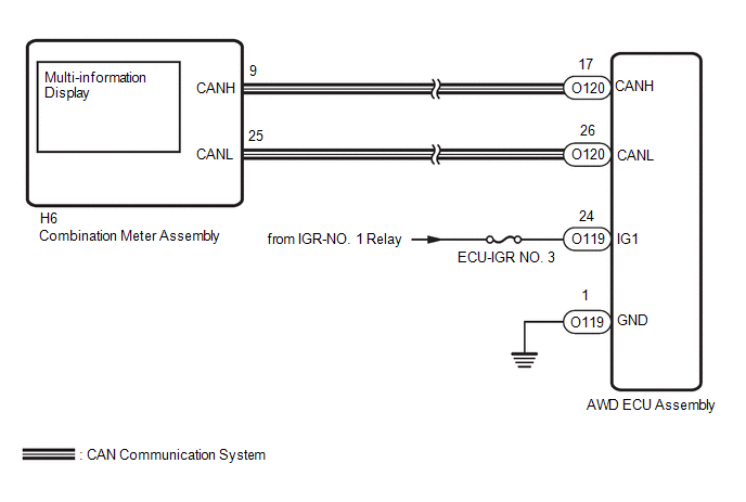
The AWD ECU assembly is connected to the combination meter assembly via the CAN communication system.
If the AWD ECU assembly stores any DTCs which are related to the active torque split AWD system, the warning message is displayed on the multi-information display in the combination meter assembly.
WIRING DIAGRAM
CAUTION / NOTICE / HINT
NOTICE:
- Inspect the fuses for circuits related to this system before performing the following inspection procedure.
-
When the AWD ECU assembly is replaced, before removing the AWD ECU assembly, it is necessary to perform ECU Data Save to save the original AWD ECU assembly information.
Click here

HINT:
Check the condition of each related circuit connector before troubleshooting.
Click here

PROCEDURE
| 1. | CHECK VEHICLE CONTROL HISTORY (ACTIVE TORQUE SPLIT AWD SYSTEM) |
(a) Using the GTS, check for Vehicle Control History.
Click here

| Tester Display |
|---|
| Vehicle Control History (RoB) |
HINT:
If vehicle control history is stored when the active torque split AWD system are suspended, the warning message is displayed.
| Result | Proceed to |
|---|---|
| There is no vehicle control history for when the active torque split AWD system were suspended. | A |
| There is vehicle control history for when the active torque split AWD system were suspended. | B |
| B |
 | PERFORM TROUBLESHOOTING AND REPAIR REGARDING VEHICLE CONTROL HISTORY |
|

| 2. | CHECK IF AWD ECU ASSEMBLY CONNECTOR IS SECURELY CONNECTED |
(a) Check that there is no looseness at the locking and connecting parts of the AWD ECU assembly connector.
(b) Disconnect the O119 and O120 AWD ECU assembly connectors.
(c) Check the connector case and the terminal for deformation and corrosion.
OK:
No deformation or corrosion
(d) Connect the O119 and O120 AWD ECU assembly connectors.
| NG |
 | CONNECT CONNECTOR TO ECU CORRECTLY |
|

| 3. | CHECK HARNESS AND CONNECTOR (IG1 TERMINAL) |
(a) Turn the ignition switch off.
(b) Disconnect the O119 AWD ECU assembly connector.
(c) Turn the ignition switch to ON.
(d) Measure the voltage according to the value(s) in the table below.
Standard Voltage:
| Tester Connection | Switch Condition | Specified Condition |
|---|---|---|
| O119-24 (IG1) - Body ground | Ignition switch ON | 11 to 14 V |
| NG |
 | REPAIR OR REPLACE HARNESS OR CONNECTOR |
|

| 4. | CHECK HARNESS AND CONNECTOR (GND TERMINAL) |
(a) Turn the ignition switch off.
(b) Disconnect the O119 AWD ECU assembly connector.
(c) Measure the resistance according to the value(s) in the table below.
Standard Resistance:
| Tester Connection | Condition | Specified Condition |
|---|---|---|
| O119-1 (GND) - Body ground | Always | Below 1 Ω |
| NG |
 | REPAIR OR REPLACE HARNESS OR CONNECTOR |
|

| 5. | READ VALUE USING GTS (AWD WARNING LIGHT) |
(a) According to the display on the GTS, read the Data List.
Chassis > Four Wheel Drive > Data List| Tester Display | Measurement Item | Range | Normal Condition | Diagnostic Note |
|---|---|---|---|---|
| 4WD Warning Light | AWD warning (multi-information display) | OFF / ON | OFF: Warning off ON: Warning on | - |
| Tester Display |
|---|
| 4WD Warning Light |
(b) Check the GTS display condition of the AWD warning light.
| Result | Proceed to |
|---|---|
| Display of the Data List remains OFF | A |
| Display of the Data List remains ON | B |
| A |
 | GO TO METER / GAUGE SYSTEM (HOW TO PROCEED WITH TROUBLESHOOTING) |
| B |
 | REPLACE AWD ECU ASSEMBLY |
 Lost Communication with ECM/PCM "A" Missing Message (U010087,U012687,U012987)
DESCRIPTION The AWD ECU assembly receives signals from the ECM, steering sensor and skid control ECU (brake actuator assembly) via CAN communication. DTC No...
 AWD Warning Light does not Come ON
DESCRIPTION Refer to "AWD Warning Light Remains ON". Click here
WIRING DIAGRAM Refer to "AWD Warning Light Remains ON". Click here
CAUTION / NOTICE / HINT Refer to "AWD Warning Light Remains ON"...
Other information:
Toyota Yaris XP210 (2020-2026) Reapir and Service Manual: Tire And Wheel
C..
Toyota Yaris XP210 (2020-2026) Reapir and Service Manual: Removal
REMOVAL CAUTION / NOTICE / HINT The necessary procedures (adjustment, calibration, initialization, or registration) that must be performed after parts are removed and installed, or replaced during the power steering ECU assembly removal/installation are shown below...
Categories
- Manuals Home
- Toyota Yaris Owners Manual
- Toyota Yaris Service Manual
- Engine Start Function When Key Battery is Dead
- Diagnostic Trouble Code Chart
- Headlights
- New on site
- Most important about car
Front Seat Belt Pretensioners
The front seat belt pretensioners are designed to deploy in moderate or severe frontal, near frontal collisions.
In addition, the pretensioners operate when a side collision or a rollover accident is detected. The pretensioners operate differently depending on what types of air bags are equipped. For more details about the seat belt pretensioner operation, refer to the SRS Air Bag Deployment Criteria.