Toyota Yaris: Meter / Gauge System / Fuel Receiver Gauge Malfunction
DESCRIPTION
FUEL RECEIVER GAUGE OPERATION
(a) OPERATION
The combination meter assembly uses the fuel sender gauge assembly to detect the amount of fuel remaining in the fuel tank assembly. The Hall IC built into the fuel sender gauge assembly changes the output voltage according to the amount of fuel remaining. The combination meter assembly receives fuel consumption signals from the ECM and detects the voltage output from the fuel sender gauge assembly and operates the fuel receiver gauge.
FUEL RECEIVER GAUGE READING
(a) During normal driving:
While driving, the fuel level indicated by the fuel receiver gauge decreases according to the fuel consumed. As the fuel level in the fuel tank may be unstable depending on the driving conditions, the combination meter assembly corrects the fuel receiver gauge reading based on the fluctuations in the fuel level.
(b) During refueling:
When fuel is added to the fuel tank, if the fuel level increases by a certain amount or more, the output of the fuel sender gauge assembly will change. The combination meter assembly detects this change and determines that refueling has been performed and calculates the volume of fuel added. This is called refueling judgment. The combination meter assembly adjusts the fuel receiver gauge reading based on the refueling judgment.
NOTICE:
Add fuel with the ignition switch off to ensure safety and to enable refueling judgment so that an appropriate fuel receiver gauge reading will be obtained.
REFUELING JUDGMENT CONDITIONS
(a) Normal judgment condition (When normal refueling method is used)
- With the ignition switch off, the fuel sender gauge assembly detects a change of 5.0 liters (5.3 US qts, 4.4 Imp. qts) or more in the fuel level.
(b) Other judgment conditions (When other refueling method is used)
- With the ignition switch ON and the vehicle and engine stopped, the fuel sender gauge assembly detects a change of 5.0 liters (5.3 US qts, 4.4 Imp. qts) or more in the fuel level.
PRECAUTION FOR REFUELING
(a) The fuel sender gauge assembly cannot detect changes in the fuel level within certain ranges (around points E and F). Therefore, even if the refueling judgment conditions are satisfied, the fuel receiver gauge reading may not change when the fuel level is within either range.
(b) When refueling judgment is performed, it takes up to approximately 25 seconds for the fuel receiver gauge reading to change to the appropriate level.
FORCED RESET OF FUEL RECEIVER GAUGE
When refueling judgment conditions are not met, if the output of the fuel sender gauge assembly and the fuel receiver gauge reading differ by 15.0 liters (15.9 US qts, 13.2 Imp. qts) or more for approximately 5 minutes continuously, the fuel receiver gauge reading will reflect the detected fuel level without correction and it may take up to approximately 25 seconds for the reading to change to the appropriate level.
CAUTION / NOTICE / HINT
NOTICE:
- When replacing the combination meter assembly, always replace it with a new one. If a combination meter assembly which was installed to another vehicle is used, the information stored in it will not match the information from the vehicle and a DTC may be stored.
-
Before preforming this procedure, check for Meter / Gauge System DTC B150013 or B150113 which is stored if an open or short in the circuit is detected. If DTC B150013 or B150113 is output, perform troubleshooting and repairs as necessary.
Click here

HINT:
When the fuel level drops below the following amount, the fuel level warning light illuminates.
- 6.0 liters (6.3 US qts, 5.3 Imp. qts)
PROCEDURE
| 1. | CHECK FOR DTC (SFI SYSTEM) |
(a) Check if SFI system DTCs are output.
Powertrain > Engine > Trouble Codes| Result | Proceed to |
|---|---|
| DTCs are not output | A |
| DTCs are output | B |
| B |
 | GO TO SFI SYSTEM |
|

| 2. | CHECK FOR DTC (VEHICLE STABILITY CONTROL SYSTEM) |
(a) Check if vehicle stability control system DTCs are output.
Chassis > Brake > Trouble Codes| Result | Proceed to |
|---|---|
| DTCs are not output | A |
| DTCs are output | B |
| B |
 | GO TO VEHICLE STABILITY CONTROL SYSTEM |
|

| 3. | CHECK FOR DTC (METER / GAUGE SYSTEM) |
(a) Check if DTC B150013 or B150113 is output.
Body Electrical > Combination Meter > Trouble Codes| Result | Proceed to |
|---|---|
| B150013 or B150113 is not output | A |
| B150013 or B150113 is output | B |
| B |
 | GO TO B150013 OR B150113 |
|

| 4. | CHECK SYMPTOMS |
(a) Ask the customer about the problem symptoms.
| Result | Proceed to |
|---|---|
| Malfunction occurs when adding fuel (Even when refueled, display value does not increase) | A |
| Malfunction occurs when adding fuel (When refueled, display value increase is slow) | B |
| Malfunction occurs during normal driving (The reading does not change, decreases quickly or decreases when the vehicle is not being driven, etc.) (The problem symptom recurs) | C |
| Malfunction occurs during normal driving (The reading does not change, decreases quickly or decreases when the vehicle is not being driven, etc.) (The problem symptom does not recur) | D |
| B |
 | GO TO STEP 6 |
| C |
 | GO TO STEP 8 |
| D |
 | GO TO STEP 10 |
|

| 5. | MANUALLY UPDATE FUEL RECEIVER GAUGE |
(a) Perform a manual update of the fuel receiver gauge.
Click here

(b) Check that the display value of the fuel receiver gauge has changed.
| OK |
 | END |
| NG |
 | GO TO STEP 6 |
| 6. | PERFORM ACTIVE TEST USING GTS |
(a) Perform the Active Test according to the display on the GTS.
Body Electrical > Combination Meter > Active Test| Tester Display | Measurement Item | Control Range | Diagnostic Note |
|---|---|---|---|
| Fuel Gauge Operation (Sender E) | Fuel receiver gauge (Fuel sender gauge lower limit) | ON | See [Display 1] |
| Fuel Gauge Operation (Empty) | Fuel receiver gauge (Fuel receiver gauge indicates E) | ON | See [Display 1] |
| Fuel Gauge Operation (Warning) | Fuel receiver gauge (Position at which fuel level warning light turns on/off) | ON | See [Display 1] |
| Fuel Gauge Operation (1/4) | Fuel receiver gauge (Fuel receiver gauge indicates 1/4) | ON | See [Display 1] |
| Fuel Gauge Operation (1/2) | Fuel receiver gauge (Fuel receiver gauge indicates 1/2) | ON | See [Display 1] |
| Fuel Gauge Operation (3/4) | Fuel receiver gauge (Fuel receiver gauge indicates 3/4) | ON | See [Display 1] |
| Fuel Gauge Operation (Full) | Fuel receiver gauge (Fuel receiver gauge indicates F) | ON | See [Display 1] |
| Fuel Gauge Operation (Sender F) | Fuel receiver gauge (Fuel sender gauge upper limit) | ON | See [Display 1] |
-

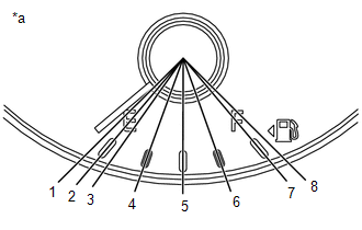
*a
Fuel Receiver Gauge
HINT:
Refer to the following table for the specified fuel receiver gauge position for each selected value:
Tester Display
Fuel Receiver Gauge Indication
Fuel Gauge Operation
(Sender E)
Approximately 1 is indicated
Fuel Gauge Operation
(Empty)
Approximately 2 is indicated
Fuel Gauge Operation
(Warning)
Approximately 3 is indicated
Fuel Gauge Operation
(1/4)
Approximately 4 is indicated
Fuel Gauge Operation
(1/2)
Approximately 5 is indicated
Fuel Gauge Operation
(3/4)
Approximately 6 is indicated
Fuel Gauge Operation
(Full)
Approximately 7 is indicated
Fuel Gauge Operation
(Sender F)
Approximately 8 is indicated
| Tester Display |
|---|
| Fuel Gauge Operation (Sender E) |
| Tester Display |
|---|
| Fuel Gauge Operation (Empty) |
| Tester Display |
|---|
| Fuel Gauge Operation (Warning) |
| Tester Display |
|---|
| Fuel Gauge Operation (1/4) |
| Tester Display |
|---|
| Fuel Gauge Operation (1/2) |
| Tester Display |
|---|
| Fuel Gauge Operation (3/4) |
| Tester Display |
|---|
| Fuel Gauge Operation (Full) |
| Tester Display |
|---|
| Fuel Gauge Operation (Sender F) |
OK:
Fuel receiver gauge indication is normal.
| NG |
 | REPLACE COMBINATION METER ASSEMBLY |
|

| 7. | CHECK FUEL RECEIVER GAUGE (OPERATION BY ADDING FUEL) |
(a) If the fuel tank assembly is almost full, drain 20 liters (21.1 US qts, 17.6 Imp. qts) or more of fuel.
HINT:
This is not necessary when the fuel tank assembly is sufficiently below full.
(b) Record the fuel receiver gauge reading.
(c) Turn the ignition switch off.
(d) Disconnect the cable from the negative (-) auxiliary battery terminal to reset the fuel receiver gauge.
(e) Connect the cable to the negative (-) auxiliary battery terminal.
(f) Turn the ignition switch to ON.
(g) Drive the vehicle at 1.8 km/h (1 mph) or more, then stop the vehicle.
(h) Turn the ignition switch off.
(i) Add 5.0 liters (5.3 US qts, 4.4 Imp. qts) or more of fuel.
(j) Turn the ignition switch to ON.
(k) Check that the fuel receiver gauge reading increases in proportion to the amount of fuel added.
| Result | Proceed to |
|---|---|
| Fuel receiver gauge reading increases in proportion to the amount of fuel added | A |
| Fuel receiver gauge reading does not change even when fuel is added | B |
| A |
 | GO TO STEP 10 |
| B |
 | REPLACE COMBINATION METER ASSEMBLY |
| 8. | PERFORM ACTIVE TEST USING GTS |
(a) Perform the Active Test according to the display on the GTS.
Body Electrical > Combination Meter > Active Test| Tester Display | Measurement Item | Control Range | Diagnostic Note |
|---|---|---|---|
| Fuel Gauge Operation (Sender E) | Fuel receiver gauge (Fuel sender gauge lower limit) | ON | See [Display 1] |
| Fuel Gauge Operation (Empty) | Fuel receiver gauge (Fuel receiver gauge indicates E) | ON | See [Display 1] |
| Fuel Gauge Operation (Warning) | Fuel receiver gauge (Position at which fuel level warning light turns on/off) | ON | See [Display 1] |
| Fuel Gauge Operation (1/4) | Fuel receiver gauge (Fuel receiver gauge indicates 1/4) | ON | See [Display 1] |
| Fuel Gauge Operation (1/2) | Fuel receiver gauge (Fuel receiver gauge indicates 1/2) | ON | See [Display 1] |
| Fuel Gauge Operation (3/4) | Fuel receiver gauge (Fuel receiver gauge indicates 3/4) | ON | See [Display 1] |
| Fuel Gauge Operation (Full) | Fuel receiver gauge (Fuel receiver gauge indicates F) | ON | See [Display 1] |
| Fuel Gauge Operation (Sender F) | Fuel receiver gauge (Fuel sender gauge upper limit) | ON | See [Display 1] |
-
*a
Fuel Receiver Gauge
HINT:
Refer to the following table for the specified fuel receiver gauge position for each selected value:
Tester Display
Fuel Receiver Gauge Indication
Fuel Gauge Operation
(Sender E)
Approximately 1 is indicated
Fuel Gauge Operation
(Empty)
Approximately 2 is indicated
Fuel Gauge Operation
(Warning)
Approximately 3 is indicated
Fuel Gauge Operation
(1/4)
Approximately 4 is indicated
Fuel Gauge Operation
(1/2)
Approximately 5 is indicated
Fuel Gauge Operation
(3/4)
Approximately 6 is indicated
Fuel Gauge Operation
(Full)
Approximately 7 is indicated
Fuel Gauge Operation
(Sender F)
Approximately 8 is indicated
| Tester Display |
|---|
| Fuel Gauge Operation (Sender E) |
| Tester Display |
|---|
| Fuel Gauge Operation (Empty) |
| Tester Display |
|---|
| Fuel Gauge Operation (Warning) |
| Tester Display |
|---|
| Fuel Gauge Operation (1/4) |
| Tester Display |
|---|
| Fuel Gauge Operation (1/2) |
| Tester Display |
|---|
| Fuel Gauge Operation (3/4) |
| Tester Display |
|---|
| Fuel Gauge Operation (Full) |
| Tester Display |
|---|
| Fuel Gauge Operation (Sender F) |
OK:
Fuel receiver gauge indication is normal.
| NG |
 | REPLACE COMBINATION METER ASSEMBLY |
|

| 9. | CHECK FUEL RECEIVER GAUGE |
(a) Disconnect the cable from the negative (-) auxiliary battery terminal to reset the fuel receiver gauge.
NOTICE:
Make sure that the power switch is off before disconnecting the cable from the negative (-) auxiliary battery terminal.
(b) Connect the cable to the negative (-) auxiliary battery terminal and turn the ignition switch ON.
(c) Check if the fuel receiver gauge reading corresponds with the amount of fuel remaining in the fuel tank assembly.
| Result | Proceed to |
|---|---|
| Fuel receiver gauge reading corresponds with the amount of fuel remaining in the fuel tank assembly | A |
| Fuel receiver gauge reading does not correspond with the amount of fuel remaining in the fuel tank assembly | B |
| A |
 | END |
| B |
 | REPLACE COMBINATION METER ASSEMBLY |
| 10. | INSPECT FUEL TANK SUB-ASSEMBLY |
HINT:
Inspect the fuel tank assembly and fuel sender assembly for deformation, foreign matter or an improperly installed fuel receiver gauge, as this may be the cause of the fuel receiver gauge malfunction.
(a) Visually check the fuel tank sub-assembly for any abnormalities.
(b) Check if there is an excessive amount of foreign matter in the fuel tank sub-assembly.
(c) Visually check the fuel sender gauge assembly and No. 2 fuel sender gauge assembly for damage and confirm that it operates correctly.
(d) Check the installation condition of the fuel tank assembly fuel sender gauge assembly and No. 2 fuel sender gauge assembly.
| Result | Proceed to |
|---|---|
| Normal | A |
| Appearance of the fuel tank sub-assembly is abnormal | B |
| There is an excessive amount of foreign matter in the fuel tank sub-assembly | C |
| The fuel sender gauge assembly is visually damaged or does not operate correctly | D |
| The No. 2 fuel sender gauge assembly is visually damaged or does not operate correctly | E |
| The fuel tank sub-assembly or fuel sender gauge assembly is not installed correctly | F |
| A |
 | REPLACE COMBINATION METER ASSEMBLY |
| B |
 | REPLACE FUEL TANK SUB-ASSEMBLY |
| C |
 | CLEAN INSIDE OF FUEL TANK SUB-ASSEMBLY |
| D |
 | REPLACE FUEL SENDER GAUGE ASSEMBLY |
| E |
 | REPLACE NO. 2 FUEL SENDER GAUGE ASSEMBLY |
| F |
 | INSTALL FUEL TANK ASSEMBLY OR FUEL SENDER GAUGE ASSEMBLY CORRECTLY |
 Tachometer Malfunction
DESCRIPTION In this circuit, the combination meter assembly receives engine speed signals from the ECM via CAN communication. The combination meter assembly displays the engine speed calculated based on the data received from the ECM...
 Engine Coolant Temperature Receiver Gauge Malfunction
DESCRIPTION In this circuit, the combination meter assembly receives engine coolant temperature signals from the ECM via CAN communication. The combination meter assembly displays an engine coolant temperature warning based on the data received from the ECM...
Other information:
Toyota Yaris XP210 (2020-2026) Reapir and Service Manual: Components
COMPONENTS ILLUSTRATION *1 REAR AXLE HUB BOLT *2 REAR DISC *3 REAR DISC BRAKE CALIPER ASSEMBLY *4 REAR FLEXIBLE HOSE *5 PARKING BRAKE SHOE ADJUSTING HOLE PLUG - - Tightening torque for "Major areas involving basic vehicle performance such as moving/turning/stopping" : N*m (kgf*cm, ft...
Toyota Yaris XP210 (2020-2026) Reapir and Service Manual: Clutch Pedal Switch "A" Circuit Short to Ground (P083011)
DESCRIPTION HINT: This DTC is applicable to Manual Transaxle models only. The clutch stroke sensor assembly (for detecting pedal depression amount) and clutch switch assembly (for detecting the pedal depression endpoint) are installed to the clutch pedal...
Categories
- Manuals Home
- Toyota Yaris Owners Manual
- Toyota Yaris Service Manual
- Auto Lock/Unlock Function
- Diagnostic Trouble Code Chart
- G16e-gts (engine Mechanical)
- New on site
- Most important about car
Turning the Engine Off
Stop the vehicle completely. Manual transaxle: Shift into neutral and set the parking brake.Automatic transaxle: Shift the selector lever to the P position and set the parking brake.
Press the push button start to turn off the engine. The ignition position is off.