
Toyota Yaris: G16e-gts (lubrication) / Engine Oil Cooler
Components
COMPONENTS
ILLUSTRATION
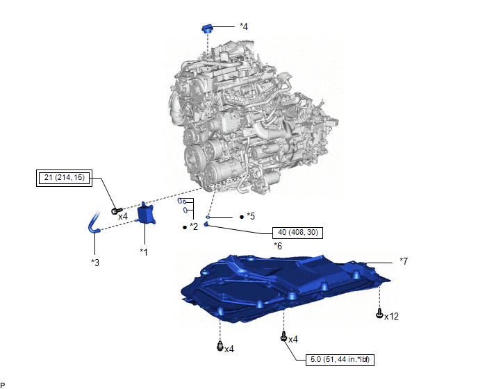
| *1 | OIL COOLER ASSEMBLY | *2 | OIL COOLER GASKET |
| *3 | NO. 5 WATER BY-PASS HOSE | *4 | OIL FILLER CAP ASSEMBLY |
| *5 | GASKET | *6 | OIL PAN DRAIN PLUG |
| *7 | NO. 1 ENGINE UNDER COVER ASSEMBLY | - | - |
 | Tightening torque for "Major areas involving basic vehicle performance such as moving/turning/stopping": N*m (kgf*cm, ft.*lbf) |
 | N*m (kgf*cm, ft.*lbf): Specified torque |
| ● | Non-reusable part | - | - |
Inspection
INSPECTION
PROCEDURE
1. INSPECT OIL COOLER ASSEMBLY
(a) Visually check the oil cooler assembly for cracks or damage.
If cracks or damage are found, replace the oil cooler assembly.
Removal
REMOVAL
PROCEDURE
1. REMOVE NO. 1 ENGINE UNDER COVER ASSEMBLY
Click here

2. DRAIN ENGINE COOLANT
Click here

3. DRAIN ENGINE OIL
Click here

4. REMOVE OIL COOLER ASSEMBLY
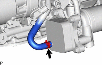
| (a) Slide the clip and disconnect the No. 5 water by-pass hose from the oil cooler assembly. |
|
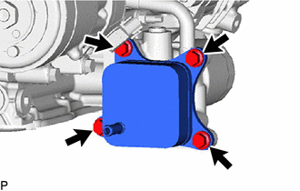
| (b) Remove the 4 bolts and oil cooler assembly from the oil filter bracket sub-assembly. |
|
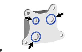
| (c) Remove the 3 oil cooler gaskets from the oil cooler assembly. |
|
Installation
INSTALLATION
PROCEDURE
1. INSTALL OIL COOLER ASSEMBLY
(a) Install 3 new oil cooler gaskets to the oil cooler assembly.
(b) Install the oil cooler assembly to the oil filter bracket sub-assembly with the 4 bolts.
Torque:
21 N·m {214 kgf·cm, 15 ft·lbf}
(c) Connect the No. 5 water by-pass hose to the oil cooler assembly, and slide the clip to secure them.
2. ADD ENGINE OIL
Click here

3. ADD ENGINE COOLANT
Click here

4. INSPECT FOR COOLANT LEAK
Click here

5. CHECK ENGINE OIL LEVEL
Click here

6. INSPECT FOR ENGINE OIL LEAK
Click here

7. INSTALL NO. 1 ENGINE UNDER COVER ASSEMBLY
Click here


 Lubrication System
On-vehicle InspectionON-VEHICLE INSPECTION PROCEDURE 1. CHECK ENGINE OIL LEVEL (a) Warm up and stop the engine, then wait for 5 minutes. (b) Check that the engine oil level is between the low level and full level marks on the engine oil level dipstick...
Other information:
Toyota Yaris XP210 (2020-2026) Reapir and Service Manual: Driver Side Door Entry Lock Function does not Operate
DESCRIPTION If the entry lock function does not operate for the driver door only, but the entry unlock function operates, the request code is being transmitted properly from the driver door. In this case, there may be a problem related to the lock sensor (connection between the certification ECU (smart key ECU assembly) and front door outside handle assembly LH)...
Toyota Yaris XP210 (2020-2026) Reapir and Service Manual: Terminals Of Ecu
TERMINALS OF ECU CHECK STEREO COMPONENT EQUALIZER ASSEMBLY Terminal No. (Symbol) Terminal Description Condition Specified Condition O131-15(+B) - O131-30(GND) Power source Always 11 to 14 V O131-29(IGP) - O131-30(GND) Power source (IG) Ignition switch ON 11 to 14 V O131-14(ACC) - O131-30(GND) Power source (ACC) Ignition switch ACC 11 to 14 V O131-30(GND) - Body ground Ground Always Below 1 Ω O132-1(MC1+) - O131-30(GND) Active noise control microphone input signal Active noise control microphone LH tapped with finger Pulse generation O132-5(MC1-) - O131-30(GND) Active noise control microphone input signal Always Below 1 Ω O132-2(MC2+) - O131-30(GND) Active noise control microphone input signal Active noise control microphone RH tapped with finger Pulse generation O132-6(MC2-) - O131-30(GND) Active noise control microphone input signal Always Below 1 Ω O131-3(NEI) - O131-30(GND) Engine pulse signal Idling with warm engine Pulse generation (See waveform 1) O131-24(FLI-) Active noise control microphone output signal - - O131-9(FLI+) Active noise control microphone output signal - - O131-23(FRI-) Active noise control microphone output signal - - O131-8(FRI+) Active noise control microphone output signal - - O131-5(RRI+) Active noise control microphone output signal - - O131-20(RRI-) Active noise control microphone output signal - - O131-6(RLI+) Active noise control microphone output signal - - O131-21(RLI-) Active noise control microphone output signal - - O131-7(ASG1) Shield ground - - O131-22(ASG2) Shield ground - - O131-12(FR+) - O131-30(GND) Sound signal Active noise control system operating Pulse generation O131-27(FR-) - O131-30(GND) Sound signal Active noise control system operating Pulse generation O131-13(FL+) - O131-30(GND) Sound signal Active noise control system operating Pulse generation O131-28(FL-) - O131-30(GND) Sound signal Active noise control system operating Pulse generation O131-10(RR+) - O131-30(GND) Sound signal Active noise control system operating Pulse generation O131+25(RR-) - O131-30(GND) Sound signal Active noise control system operating Pulse generation O131-11(RL+) - O131-30(GND) Sound signal Active noise control system operating Pulse generation O131-28(RL-) - O131-30(GND) Sound signal Active noise control system operating Pulse generation O131-1(CANH) CAN communication signal - - O131-16(CANL) CAN communication signal - - (a) Waveform 1 HINT: The oscilloscope waveform shown in the illustration is an example for reference only...
Categories
- Manuals Home
- Toyota Yaris Owners Manual
- Toyota Yaris Service Manual
- Fuel Gauge
- G16e-gts (engine Mechanical)
- Immobilizer System
- New on site
- Most important about car
Supplemental Restraint System (SRS) Precautions
The front and side supplemental restraint systems (SRS) include different types of air bags. Please verify the different types of air bags which are equipped on your vehicle by locating the “SRS AIRBAG” location indicators. These indicators are visible in the area where the air bags are installed.
The air bags are installed in the following locations:
The steering wheel hub (driver air bag) The front passenger dashboard (front passenger air bag) The outboard sides of the front seatbacks (side air bags) The front and rear window pillars, and the roof edge along both sides (curtain air bags)