Toyota Yaris: Theft Deterrent / Keyless Entry / Electrical Key Oscillator (for Front Floor)
Components
COMPONENTS
ILLUSTRATION
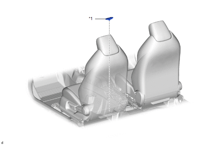
| *1 | NO. 1 INDOOR ELECTRICAL KEY ANTENNA ASSEMBLY | - | - |
Removal
REMOVAL
PROCEDURE
1. REMOVE REAR CONSOLE BOX ASSEMBLY
Click here

2. REMOVE NO. 1 INDOOR ELECTRICAL KEY ANTENNA ASSEMBLY
| (a) Disconnect the connector. |
|
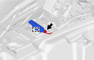
(b) Using a clip remover,disengage the clamp to remove the No. 1 indoor electrical key antenna assembly.
NOTICE:
Be careful when removing the No. 1 indoor electrical key antenna assembly. If the No. 1 indoor electrical key antenna assembly is dropped, replace it with a new one.
Installation
INSTALLATION
PROCEDURE
1. INSTALL NO. 1 INDOOR ELECTRICAL KEY ANTENNA ASSEMBLY
(a) Engage the clamp to install the No. 1 indoor electrical key antenna assembly.
NOTICE:
Be careful when installing the No. 1 indoor electrical key antenna assembly. If the No. 1 indoor electrical key antenna assembly is dropped, replace it with a new one.
(b) Connect the connector.
2. INSTALL REAR CONSOLE BOX ASSEMBLY
Click here

 Certification Ecu
ComponentsCOMPONENTS ILLUSTRATION
*1 CERTIFICATION ECU (SMART KEY ECU ASSEMBLY) - - RemovalREMOVAL CAUTION / NOTICE / HINT The necessary procedures (adjustment, calibration, initialization, or registration) that must be performed after parts are removed, installed, or replaced during the certification ECU (smart key ECU assembly) removal/installation are shown below...
 Electrical Key Oscillator (for Outside Luggage Compartment)
ComponentsCOMPONENTS ILLUSTRATION
*1 ELECTRICAL KEY ANTENNA - -
N*m (kgf*cm, ft.*lbf): Specified torque - - RemovalREMOVAL PROCEDURE 1...
Other information:
Toyota Yaris XP210 (2020-2026) Reapir and Service Manual: Installation
INSTALLATION PROCEDURE 1. INSTALL BRAKE MASTER CYLINDER O-RING (a) Install a new brake master cylinder O-ring to the brake master cylinder sub-assembly. 2. INSTALL BRAKE MASTER CYLINDER SUB-ASSEMBLY NOTICE: When installing a new brake master cylinder sub-assembly, remove the protectors from the master cylinder piston and outlet ports...
Toyota Yaris XP210 (2020-2026) Reapir and Service Manual: Components
C..
Categories
- Manuals Home
- Toyota Yaris Owners Manual
- Toyota Yaris Service Manual
- Immobilizer System
- To Set Speed
- Adjustment
- New on site
- Most important about car
Fuel Gauge
The fuel gauge shows approximately how much fuel is remaining in the tank when the ignition is switched ON. We recommend keeping the tank over 1/4 full.
