Toyota Yaris: When Replacing Or Removing/installing Parts / Ecu Configuration
ECU CONFIGURATION
STABILIZE A POWER SOURCE ON THE VEHICLE SIDE
Shut off as many following systems and parts as possible since they would generate an electrical load.
CAUTION:
If vehicle systems affect a voltage to reduce during reprogramming, it may disable the ECU in reprogramming, which concludes an ECU replacement.
(a) Turn off all systems that add electrical load.
HINT:
- Exterior lighting systems
- Interior lighting systems (Make them unlit even when a door is open)
- Air conditioning system
- Audio/Navigation systems
- Seat belt warning system (Lock belt buckles by inserting tongue plates)
- Accessory parts of aftermarket installation
- Other, generic electrical parts (such as remote engine starter, security system)
(b) Remove the fuse or relay for the electric fan.
INSPECT THE AUXILIARY BATTERY OF THE VEHICLE. (CHECK IF IT HAS 11.8 V MIN. OF VOLTAGE.)
(a) Conduct the inspection on the vehicle battery keeping the IG-ON condition after one minute of leaving with the IG on. Check if it has 11.8 V or more of voltage.
In case of the battery weak, charge it before reprogramming.
(The inspection can be performed with no wait as one minute has already passed in the IG-ON condition if keeping the IG on from the previous step.)
CAUTION:
- If the reprogramming is conducted with a weak vehicle battery, an auxiliary charge does not prevent a voltage drop, which may disable the ECU in reprogramming and damage it.
- Be sure to use the battery tester by connecting to a terminal on the vehicle directly.
HINT:
In case of the vehicle battery placed in a compartment, inspect the battery through the terminals for rescue.
CONNECT BATTERY CHARGER TO AUXILIARY BATTERY.
(a) Connect a battery charger.
CAUTION:
- When manually setting the current settings of the battery charger, be careful not to overcharge the battery.
- A fuse may blow if the battery charger is on when the battery charger is connected to the vehicle. Make sure that the battery charger is off when the battery charger is connected to the vehicle.
(1) Turn the battery charger off.
(2) Connect the positive cable of the battery charger to the positive terminal (+) of the auxiliary battery, and connect the negative cable to an unpainted metal part of the vehicle.
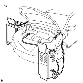
| *a | Example |
PERFORM ECU CONFIGURATION
CAUTION:
- Make sure that the ignition switch remains ON when performing ECU configuration, and that the engine is not started.
- To prevent incidents related to unauthorized persons operating the GTS or vehicle, do not leave the vehicle unattended.
- It is necessary to log in to the Toyota server to perform an ECU configration update.
- Users other than Toyota dealers can log in with a guest account issued when an ECU is ordered.
(a) Turn on the battery charger.
(b) In accordance with the display on the GTS, select and perform Health Check on the menu screen.
(c) Confirm that "Yes" is not displayed in the "Configure" column of the GTS for any system.
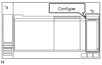
| *a | GTS Health Check Screen |
| *b | "Configure" Column |
(d) If "Yes" is displayed in the "Configure" column of the GTS for any system, click "Yes" and perform ECU configuration in accordance with the display on the GTS.
HINT:
Perform ECU Configuration for each system.
(e) After ECU configuration is complete, select and perform Health Check on the menu screen in accordance with the display on the GTS.
(f) Confirm that "Yes" is not displayed in the "Configure" column of the GTS for any system, and clear the DTCs and vehicle control history (RoB).
CAUTION:
If "Yes" is displayed in the "Configure" column of the GTS for any system, perform ECU configuration again.

 Work Procedure
WORK PROCEDURE PROCEDURES NECESSARY WHEN ECU OR OTHER PARTS ARE REPLACED Replacement Part Necessary Procedure Effect/Inoperative Function when Necessary Procedures are not Performed Link
*1: When the steering sensor is replaced with a new one, Update ECU security key is necessary...
Other information:
Toyota Yaris XP210 (2020-2026) Reapir and Service Manual: Components
COMPONENTS ILLUSTRATION *1 NO. 1 ENGINE UNDER COVER ASSEMBLY *2 ENGINE UNDER COVER RH *3 ENGINE UNDER COVER LH *4 CENTER NO. 4 ENGINE UNDER COVER N*m (kgf*cm, ft.*lbf): Specified torque - - ILLUSTRATION *1 FRONT FENDER LINER LH *2 FRONT FENDER LINER RH ILLUSTRATION *1 NO...
Toyota Yaris XP210 (2020-2026) Reapir and Service Manual: Camshaft Position "B" - Timing Over-Advanced or System Performance Bank 1 (P001400,P001500)
DESCRIPTION Refer to DTC P001313. Click here DTC No. Detection Item DTC Detection Condition Trouble Area MIL Note P001400 Camshaft Position "B" - Timing Over-Advanced or System Performance Bank 1 Exhaust valve timing is stuck at a certain value when in the advance range (2 trip detection logic)...
Categories
- Manuals Home
- Toyota Yaris Owners Manual
- Toyota Yaris Service Manual
- Engine Start Function When Key Battery is Dead
- Brake System Control Module "A" System Voltage System Voltage Low (C137BA2)
- Opening and Closing the Liftgate/Trunk Lid
- New on site
- Most important about car
Refueling
Before refueling, close all the doors, windows, and the liftgate/trunk lid, and switch the ignition OFF.
To open the fuel-filler lid, pull the remote fuel-filler lid release.
