Toyota Yaris: Door Lock / Door Control Switch
Components
COMPONENTS
ILLUSTRATION
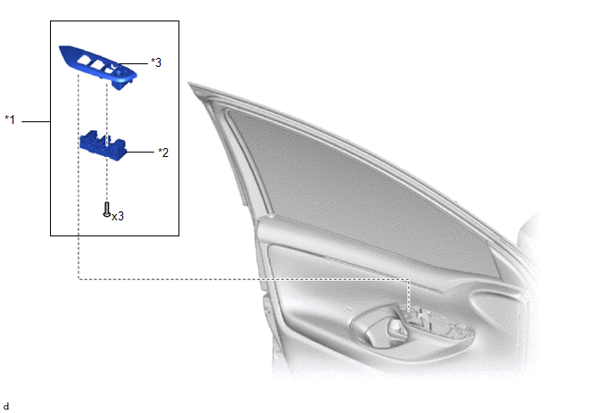
| *1 | MULTIPLEX NETWORK MASTER SWITCH ASSEMBLY WITH FRONT ARMREST BASE UPPER PANEL | *2 | MULTIPLEX NETWORK MASTER SWITCH ASSEMBLY |
| *3 | FRONT ARMREST BASE UPPER PANEL RH | - | - |
Removal
REMOVAL
PROCEDURE
1. REMOVE MULTIPLEX NETWORK MASTER SWITCH ASSEMBLY WITH FRONT ARMREST BASE UPPER PANEL
Click here

2. REMOVE MULTIPLEX NETWORK MASTER SWITCH ASSEMBLY
| (a) Remove the 3 screws and multiplex network master switch assembly. |
|

Installation
INSTALLATION
PROCEDURE
1. INSTALL MULTIPLEX NETWORK MASTER SWITCH ASSEMBLY
(a) Install the multiplex network master switch assembly with the 3 screws.
2. INSTALL MULTIPLEX NETWORK MASTER SWITCH ASSEMBLY WITH FRONT ARMREST BASE UPPER PANEL
Click here

 Door Control Receiver
ComponentsCOMPONENTS ILLUSTRATION
*1 DOOR CONTROL RECEIVER - -
N*m (kgf*cm, ft.*lbf): Specified torque - - RemovalREMOVAL PROCEDURE 1...
 Door Control Transmitter
ComponentsCOMPONENTS ILLUSTRATION
*1 MECHANICAL KEY *2 TRANSMITTER BATTERY *3 TRANSMITTER HOUSING CASE *4 TRANSMITTER HOUSING COVER InspectionINSPECTION PROCEDURE 1...
Other information:
Toyota Yaris XP210 (2020-2026) Reapir and Service Manual: Customize Parameters
CUSTOMIZE PARAMETERS INSTALL CUSTOMIZE THEFT DETERRENT SYSTEM HINT: The following items can be customized. NOTICE: When the customer requests a change in a function, first make sure that the function can be customized. Be sure to make a note of the current settings before customizing...
Toyota Yaris XP210 (2020-2026) Reapir and Service Manual: Yaw Rate Sensor Signal Bias Level Out of Range / Zero Adjustment Failure (C006328,C006396)
DESCRIPTION These DTCs are stored when the skid control ECU (brake actuator assembly) receives an internal malfunction signal from the yaw rate and acceleration sensor (airbag sensor assembly). DTC No. Detection Item DTC Detection Condition Trouble Area DTC Output from C006328 Yaw Rate Sensor Signal Bias Level Out of Range / Zero Adjustment Failure With the vehicle stationary, the yaw rate sensor output value is not 0°/s...
Categories
- Manuals Home
- Toyota Yaris Owners Manual
- Toyota Yaris Service Manual
- How to use USB mode
- Maintenance
- Fuel Gauge
- New on site
- Most important about car
Fuel Gauge
The fuel gauge shows approximately how much fuel is remaining in the tank when the ignition is switched ON. We recommend keeping the tank over 1/4 full.
