Toyota Yaris: Maintenance / Differential Oil
Components
COMPONENTS
ILLUSTRATION
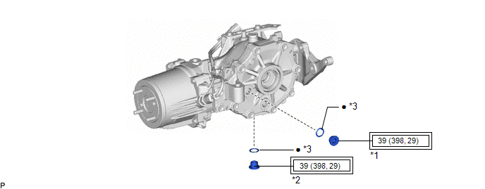
| *1 | REAR DIFFERENTIAL FILLER PLUG | *2 | REAR DIFFERENTIAL DRAIN PLUG |
| *3 | GASKET | - | - |
 | Tightening torque for "Major areas involving basic vehicle performance such as moving/turning/stopping": N*m (kgf*cm, ft.*lbf) | ● | Non-reusable part |
Replacement
REPLACEMENT
CAUTION / NOTICE / HINT
HINT:
Stop the vehicle on a level surface.
PROCEDURE
1. DRAIN DIFFERENTIAL OIL
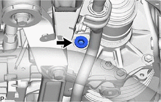
NOTICE:
-
Do not loosen the bolt shown in the illustration to drain the differential oil.
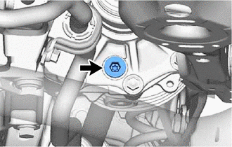
- Doing so could cause differential oil to spill onto the tail exhaust pipe assembly.
| (a) Using a 10 mm socket hexagon wrench, remove the rear differential filler plug and gasket. |
|

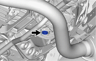
| (b) Using a 10 mm socket hexagon wrench, remove the rear differential drain plug and gasket to drain the differential oil. NOTICE: As the differential oil may be hot after driving, make sure that the differential is sufficiently cool before starting work. |
|
(c) Using a 10 mm socket hexagon wrench, install a new gasket and the rear differential drain plug.
Torque:
39 N·m {398 kgf·cm, 29 ft·lbf}
2. ADD DIFFERENTIAL OIL
(a) Add differential oil.
Oil Type:
Toyota Genuine Differential gear oil LX 75W-85 GL-5 or equivalent
Standard Differential Oil Capacity:
0.45 to 0.55 liters (0.48 to 0.58 US qts., 0.40 to 0.48 Imp. qts.)
NOTICE:
- Using differential gear oil other than the specified oil may cause abnormal noise or vibration, or damage the differential gear of your vehicle.
- Add the differential oil in small quantities every few minutes.
- Too much or too little oil will lead to differential problems.
| (b) Check that the oil level is between 0 to 5 mm (0 and 0.196 in.) from the bottom lip of the rear differential filler plug opening. |
|
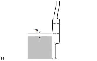
(c) Inspect for oil leaks if the oil level is low.
| (d) Using a 10 mm socket hexagon wrench, install a new gasket and the rear differential filler plug. Torque: 39 N·m {398 kgf·cm, 29 ft·lbf} NOTICE: After changing the oil, drive the vehicle and then check the oil level again. |
|
3. INSPECT FOR DIFFERENTIAL OIL LEAK
 Brake Fluid
ComponentsCOMPONENTS ILLUSTRATION
*1 CENTER COWL TOP VENTILATOR LOUVER *2 BRAKE MASTER CYLINDER RESERVOIR FILLER CAP ASSEMBLY *3 HOOD TO COWL TOP SEAL - - ILLUSTRATION
*1 FRONT DISC BRAKE BLEEDER PLUG *2 FRONT DISC BRAKE BLEEDER PLUG CAP *3 REAR DISC BRAKE BLEEDER PLUG *4 REAR DISC BRAKE BLEEDER PLUG CAP
Tightening torque for "Major areas involving basic vehicle performance such as moving/turning/stopping" : N*m (kgf*cm, ft...
 Ea67f Manual Transaxle Oil
ComponentsCOMPONENTS ILLUSTRATION
*1 NO. 1 ENGINE UNDER COVER ASSEMBLY *2 ENGINE UNDER COVER LH *3 MANUAL TRANSMISSION FILLER PLUG *4 MANUAL TRANSMISSION DRAIN PLUG *5 GASKET - -
N*m (kgf*cm, ft...
Other information:
Toyota Yaris XP210 (2020-2026) Reapir and Service Manual: Data List / Active Test
DATA LIST / ACTIVE TEST DATA LIST NOTICE: In the following table, the values listed under "Normal Condition" are reference values. Do not depend solely on these reference values when deciding whether a part is faulty or not. HINT: Using the GTS to read the Data List allows the values or states of switches, sensors, actuators and other items to be read without removing any parts...
Toyota Yaris XP210 (2020-2026) Reapir and Service Manual: Data List / Active Test
DATA LIST / ACTIVE TEST DATA LIST NOTICE: In the table below, the values listed under "Normal Condition" are reference values. Do not depend solely on these reference values when deciding whether a part is faulty or not. HINT: Using the GTS to read the Data List allows the values or states of switches, sensors, actuators and other items to be read without removing any parts...
Categories
- Manuals Home
- Toyota Yaris Owners Manual
- Toyota Yaris Service Manual
- To Set Speed
- Battery Monitor Module General Electrical Failure (P058A01)
- Engine Start Function When Key Battery is Dead
- New on site
- Most important about car
Front Seat Belt Pretensioners
The front seat belt pretensioners are designed to deploy in moderate or severe frontal, near frontal collisions.
In addition, the pretensioners operate when a side collision or a rollover accident is detected. The pretensioners operate differently depending on what types of air bags are equipped. For more details about the seat belt pretensioner operation, refer to the SRS Air Bag Deployment Criteria.