Toyota Yaris: Air Conditioning System / Evaporator Temperature Sensor Circuit Short to Battery or Open (P053515)
DESCRIPTION
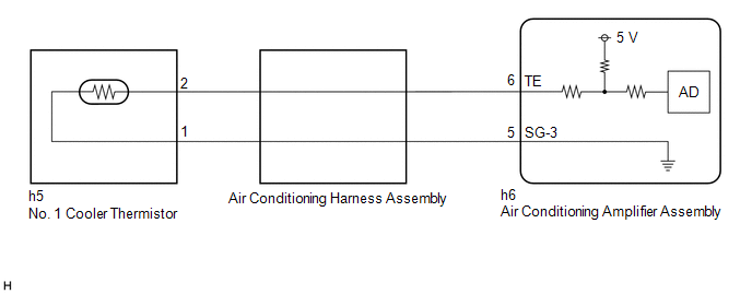
The No. 1 cooler thermistor is installed to the evaporator in the air conditioner unit to detect the temperature of the cooled air that has passed through the evaporator, which is used to control the air conditioning system. It sends signals to the air conditioning amplifier assembly. The resistance of the No. 1 cooler thermistor changes in accordance with the temperature of the cooled air that has passed through the evaporator. As the temperature decreases, the resistance increases. As the temperature increases, the resistance decreases.
The air conditioning amplifier assembly applies voltage (5 V) to the No. 1 cooler thermistor and reads voltage changes as the resistance of the No. 1 cooler thermistor changes.
| DTC No. | Detection Item | DTC Detection Condition | Trouble Area | Memory |
|---|---|---|---|---|
| P053515 | Evaporator Temperature Sensor Circuit Short to Battery or Open | Diagnosis Condition:
Malfunction Status:
Detection Time:
|
| Memorized |
| Vehicle Condition | |||
|---|---|---|---|
| Pattern 1 | Pattern 2 | ||
| Diagnosis Condition | Ignition switch ON | ○ | ○ |
| Malfunction | Open in evaporator temperature sensor circuit | ○ | - |
| Short in evaporator temperature sensor circuit | - | ○ | |
| Detection Time | Continuously for 4 seconds or more | Continuously for 4 seconds or more | |
| Trip Count | 1 trip | 1 trip | |
HINT:
If the conditions of either of these patterns are detected, a DTC will be stored
WIRING DIAGRAM
PROCEDURE
| 1. | READ VALUE USING GTS (EVAPORATOR FIN THERMISTOR) |
(a) Read the Data List according to the display on the GTS.
Body Electrical > Air Conditioner > Data List| Tester Display | Measurement Item | Normal Condition | Reference Value | Diagnostic Note |
|---|---|---|---|---|
| Evaporator Fin Thermistor | No. 1 cooler thermistor | Min.: -327.68°C (-557.82°F) Max.: 327.67°C (621.81°F) | Actual evaporator temperature displayed | No. 1 cooler thermistor circuit malfunction |
| Tester Display |
|---|
| Evaporator Fin Thermistor |
OK:
The display is as specified in the normal condition column.
| OK |
 | REPLACE AIR CONDITIONING AMPLIFIER ASSEMBLY |
|

| 2. | INSPECT NO. 1 COOLER THERMISTOR |
Click here

| NG |
 | REPLACE NO. 1 COOLER THERMISTOR |
|

| 3. | INSPECT AIR CONDITIONING HARNESS ASSEMBLY |
(a) Remove the air conditioning harness assembly.
Click here

(b) Measure the resistance according to the value(s) in the table below.
Standard Resistance:
| Tester Connection | Condition | Specified Condition |
|---|---|---|
| h5-1 - h6-5 (SG-3) | Always | Below 1 Ω |
| h5-2 - h6-6 (TE) | Always | Below 1 Ω |
| h5-1 or h6-5 (SG-3) - Other terminals and body ground | Always | 10 kΩ or higher |
| h5-2 or h6-6 (TE) - Other terminals and body ground | Always | 10 kΩ or higher |
| OK |
 | REPLACE AIR CONDITIONING AMPLIFIER ASSEMBLY |
| NG |
 | REPLACE AIR CONDITIONING HARNESS ASSEMBLY |
 Evaporator Temperature Sensor Circuit Short to Ground (P053511)
DESCRIPTION The No. 1 cooler thermistor is installed to the evaporator in the air conditioner unit to detect the temperature of the cooled air that has passed through the evaporator, which is used to control the air conditioning system...
 Lost Communication with ECM/PCM "A" Missing Message (U010087,U013187,U014087,U015587,U016387)
DESCRIPTION These DTCs are stored when the CAN communication system is malfunctioning. DTC No. Detection Item DTC Detection Condition Trouble Area Memory U010087 Lost Communication with ECM/PCM "A" Missing Message Diagnosis Condition:
IG voltage 8...
Other information:
Toyota Yaris XP210 (2020-2025) Reapir and Service Manual: Disassembly
DISASSEMBLY CAUTION / NOTICE / HINT NOTICE: Do not disconnect the tube shown in the illustration when disassembling the fuel suction tube with pump and gauge assembly. Doing so will cause reassembly of the fuel suction tube with pump and gauge assembly to be impossible as the tube is pressed into the fuel suction plate sub-assembly...
Toyota Yaris XP210 (2020-2025) Reapir and Service Manual: Outside Vehicle
OUTSIDE VEHICLE These are maintenance and inspection items that are considered to be the owner's responsibility. The owner can do them or they can have them done at a service center. These items include those that should be checked on a daily basis, those that in most cases do not require special tools, and those that are considered to be reasonable for the owner to do...
Categories
- Manuals Home
- Toyota Yaris Owners Manual
- Toyota Yaris Service Manual
- Engine Start Function When Key Battery is Dead
- Power Integration No.1 System Missing Message (B235287,B235587,B235787-B235987)
- How to connect USB port/Auxiliary jack
- New on site
- Most important about car
Front Seat Belt Pretensioners
The front seat belt pretensioners are designed to deploy in moderate or severe frontal, near frontal collisions.
In addition, the pretensioners operate when a side collision or a rollover accident is detected. The pretensioners operate differently depending on what types of air bags are equipped. For more details about the seat belt pretensioner operation, refer to the SRS Air Bag Deployment Criteria.