Toyota Yaris: Smart Key System (for Start Function) / Crankshaft Position Sensor "A" Signal Compare Failure (P033562)
DESCRIPTION
These DTCs are stored when the engine speed signal sent by the ECM via direct line and the engine speed signal sent via CAN communication do not match.
| DTC No. | Detection Item | DTC Detection Condition | Trouble Area | Note |
|---|---|---|---|---|
| P033562 | Crankshaft Position Sensor "A" Signal Compare Failure | The engine speed signal sent by the ECM via direct line and the engine speed signal sent via CAN communication do not match. (1-trip detection logic*) |
|
|
- *: Only detected while a malfunction is present and the ignition switch is ON.
| Vehicle Condition when Malfunction Detected | Fail-safe Function when Malfunction Detected |
|---|---|
|
|
| DTC No. | Data List and Active Test |
|---|---|
| P033562 | Power Source Control
|
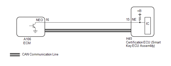
WIRING DIAGRAM
CAUTION / NOTICE / HINT
NOTICE:
- When using the GTS with the ignition switch off, connect the GTS to the DLC3 and turn a courtesy light switch on and off at intervals of 1.5 seconds or less until communication between the GTS and the vehicle begins. Then select the vehicle type under manual mode and enter the following menus: Body Electrical / Smart Key. While using the GTS, periodically turn a courtesy light switch on and off at intervals of 1.5 seconds or less to maintain communication between the GTS and the vehicle.
-
The smart key system (for Start Function) uses the LIN communication system and CAN communication system. Inspect the communication function by following How to Proceed with Troubleshooting. Troubleshoot the smart key system (for Start Function) after confirming that the communication systems are functioning properly.
Click here

-
Before replacing the certification ECU (smart key ECU assembly), refer to Registration.
Click here

- After repair, confirm that no DTCs are output by performing "DTC Output Confirmation Operation".
PROCEDURE
| 1. | READ VALUE USING GTS (ENGINE DRIVING CONDITION (LINE), ENGINE SPEED) |
(a) Read the Data List according to the display on the GTS.
Body Electrical > Power Source Control > Data List| Tester Display | Measurement Item | Range | Normal Condition | Diagnostic Note |
|---|---|---|---|---|
| Engine Driving Condition (Line) | Engine state | Stop or Driving | Stop: Engine stopped Run: Engine running | - |
| Tester Display |
|---|
| Engine Driving Condition (Line) |
| Tester Display | Measurement Item | Range | Normal Condition | Diagnostic Note |
|---|---|---|---|---|
| Engine Speed | Engine speed | 0 to 16383.75 rpm | Fluctuates in accordance with actual engine speed | - |
| Tester Display |
|---|
| Engine Speed |
OK:
The GTS display changes correctly in response to the engine condition.
| OK |
 | GO TO SFI SYSTEM |
|

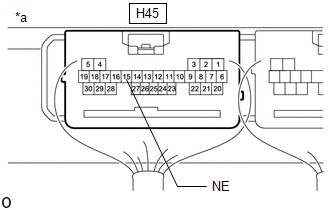
| 2. | CHECK HARNESS AND CONNECTOR (CERTIFICATION ECU (SMART KEY ECU ASSEMBLY) - ECM) |
(a) Disconnect the H45 certification ECU (smart key ECU assembly) connector.
(b) Disconnect the A106 ECM connector.
(c) Measure the resistance according to the value(s) in the table below.
Standard Resistance:
| Tester Connection | Condition | Specified Condition |
|---|---|---|
| H45-15 (NE) - A106-16 (NEO) | Always | Below 1 Ω |
| H45-15 (NE) or A106-16 (NEO) - Other terminals and body ground | Always | 10 kΩ or higher |
| NG |
 | REPAIR OR REPLACE HARNESS OR CONNECTOR |
|

| 3. | CHECK CERTIFICATION ECU (SMART KEY ECU ASSEMBLY) |
(a) Connect the H45 certification ECU (smart key ECU assembly) connector.
(b) Connect the A106 ECM connector.
| (c) Using an oscilloscope, check the engine speed input signal waveform at the terminal of the certification ECU (smart key ECU assembly). OK:
|
|
| OK |
 | REPLACE CERTIFICATION ECU (SMART KEY ECU ASSEMBLY) |
| NG |
 | GO TO SFI SYSTEM |
 Front Floor Electrical Key Oscillator Circuit Open (B27A513)
DESCRIPTION The certification ECU (smart key ECU assembly) generates a request signal and transmits the signal to the No. 1 indoor electrical key antenna assembly (front floor)...
 Lost Communication with ECM/PCM "A" Missing Message (U010087,U012987,U014087,U015587,U110387,U111787)
DESCRIPTION These DTCs are stored when there is a CAN communication malfunction between the certification ECU (smart key ECU assembly) and ECM, main body ECU (multiplex network body ECU) or combination meter assembly...
Other information:
Toyota Yaris XP210 (2020-2026) Owner's Manual: Supplemental Restraint System (SRS) Precautions
The front and side supplemental restraint systems (SRS) include different types of air bags. Please verify the different types of air bags which are equipped on your vehicle by locating the “SRS AIRBAG” location indicators. These indicators are visible in the area where the air bags are installed...
Toyota Yaris XP210 (2020-2026) Reapir and Service Manual: Low Pressure Fuel System Pressure - Too Low (P008A00)
DESCRIPTION In order to supply the optimal fuel pressure according to the driving conditions and usage environment, the variable fuel system sends a drive signal from the ECM to the fuel pump control ECU, steplessly performing variable control of the fuel pump (for low pressure side) and receiving feedback about the fuel pressure (for low pressure side) from the No...
Categories
- Manuals Home
- Toyota Yaris Owners Manual
- Toyota Yaris Service Manual
- Engine Start Function When Key Battery is Dead
- Power Integration No.1 System Missing Message (B235287,B235587,B235787-B235987)
- Headlights
- New on site
- Most important about car
Refueling
Before refueling, close all the doors, windows, and the liftgate/trunk lid, and switch the ignition OFF.
To open the fuel-filler lid, pull the remote fuel-filler lid release.
