Toyota Yaris: Front Camera / Components
COMPONENTS
ILLUSTRATION
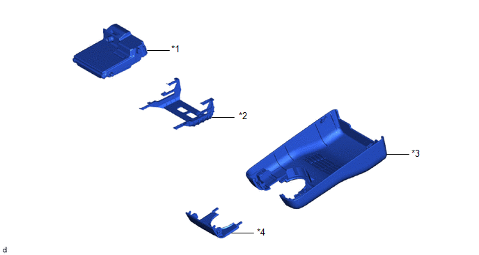
| *1 | FORWARD RECOGNITION CAMERA | *2 | FORWARD RECOGNITION LATCH |
| *3 | NO. 1 FORWARD RECOGNITION COVER | *4 | NO. 2 FORWARD RECOGNITION COVER |
 Front Camera
..
 Removal
REMOVAL CAUTION / NOTICE / HINT The necessary procedures (adjustment, calibration, initialization, or registration) that must be performed after parts are replaced during forward recognition camera removal/installation are shown below...
Other information:
Toyota Yaris XP210 (2020-2026) Reapir and Service Manual: Installation
INSTALLATION CAUTION / NOTICE / HINT HINT: Use the same procedure for the RH and LH sides. The procedure listed below is for the LH side. PROCEDURE 1. INSTALL REAR COMBINATION LIGHT ASSEMBLY (a) Connect the 3 connectors and engage the clamp...
Toyota Yaris XP210 (2020-2026) Reapir and Service Manual: Steering Angle Sensor Communication Stop Mode
DESCRIPTION Detection Item Symptom Trouble Area Steering Angle Sensor Communication Stop Mode Communication stop for "Spiral cable (Steering Angle Sensor)" is indicated on the "Communication Bus Check" screen of the GTS. Click here Steering sensor branch line or connector Power source circuit of steering sensor Steering sensor ground circuit Steering sensor WIRING DIAGRAM CAUTION / NOTICE / HINT CAUTION: When performing the confirmation driving pattern, obey all speed limits and traffic laws...
Categories
- Manuals Home
- Toyota Yaris Owners Manual
- Toyota Yaris Service Manual
- Immobilizer System
- Maintenance
- Engine Start Function When Key Battery is Dead
- New on site
- Most important about car
Fuel-Filler Lid and Cap
WARNING
When removing the fuel-filler cap, loosen the cap slightly and wait for any hissing to stop, then remove it
Fuel spray is dangerous. Fuel can burn skin and eyes and cause illness if ingested. Fuel spray is released when there is pressure in the fuel tank and the fuel-filler cap is removed too quickly.
Copyright © 2026 www.toyaris4.com