Toyota Yaris: Front Door Lock / Components
COMPONENTS
ILLUSTRATION
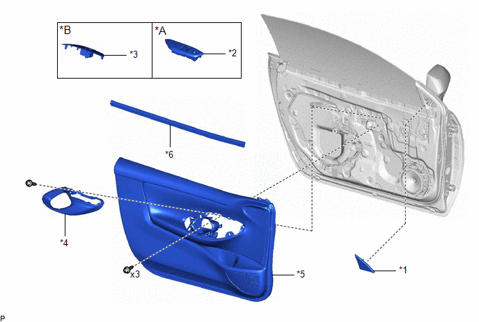
| *A | for Driver Side | *B | for Front Passenger Side |
| *1 | FRONT DOOR LOWER FRAME BRACKET GARNISH | *2 | MULTIPLEX NETWORK MASTER SWITCH ASSEMBLY WITH FRONT ARMREST BASE UPPER PANEL |
| *3 | POWER WINDOW REGULATOR SWITCH ASSEMBLY WITH FRONT ARMREST BASE UPPER PANEL | *4 | FRONT DOOR TRIM GARNISH |
| *5 | FRONT DOOR TRIM BOARD SUB-ASSEMBLY | *6 | FRONT DOOR GLASS INNER WEATHERSTRIP |
ILLUSTRATION
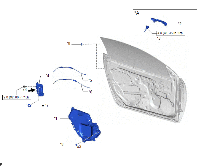
| *A | for Driver Side | - | - |
| *1 | FRONT DOOR SERVICE HOLE COVER | *2 | FRONT DOOR OUTSIDE HANDLE ASSEMBLY |
| *3 | FRONT DOOR LOCK CYLINDER ASSEMBLY | *4 | FRONT DOOR WITH MOTOR LOCK ASSEMBLY |
| *5 | FRONT DOOR LOCK OPEN LEVER REMOTE CONTROL CABLE | *6 | FRONT DOOR LOCK/UNLOCK KNOB INSIDE LOCKING CABLE |
| *7 | DOOR LOCK WIRING HARNESS SEAL | *8 | FRONT DOOR SERVICE HOLE COVER CLIP |
| *9 | HOLE PLUG | - | - |
 | N*m (kgf*cm, ft.*lbf): Specified torque | ● | Non-reusable part |
 | MP grease | - | - |

 Removal
REMOVAL CAUTION / NOTICE / HINT The necessary procedures (adjustment, calibration, initialization, or registration) that must be performed after parts are removed and installed, or replaced during the front door with motor lock assembly removal/installation are shown below...
Other information:
Toyota Yaris XP210 (2020-2026) Reapir and Service Manual: Terminals Of Ecu
TERMINALS OF ECU AIRBAG SENSOR ASSEMBLY Terminal No. Terminal Symbol Destination O24-1 ICR+ Curtain shield airbag assembly RH O24-2 ICR- O24-3 PR- Front seat outer belt assembly RH O24-4 PR+ O24-5 PL+ Front seat outer belt assembly LH O24-6 PL- O24-7 ICL- Curtain shield airbag assembly LH O24-8 ICL+ O24-9 SFR+ Front seat airbag assembly RH O24-10 SFR- O24-15 SFL- Front seat airbag assembly LH O24-16 SFL+ O24-19 BCR- No...
Toyota Yaris XP210 (2020-2026) Reapir and Service Manual: Throttle / Pedal Position Sensor / Switch "A" Circuit Short to Battery or Open (P012015)
DESCRIPTION Refer to DTC P012011. Click here DTC No. Detection Item DTC Detection Condition Trouble Area MIL Note P012015 Throttle / Pedal Position Sensor / Switch "A" Circuit Short to Battery or Open The output voltage of VTA1 is higher than 4...
Categories
- Manuals Home
- Toyota Yaris Owners Manual
- Toyota Yaris Service Manual
- Key Battery Replacement
- Brake System Control Module "A" System Voltage System Voltage Low (C137BA2)
- Fuse Panel Description
- New on site
- Most important about car
Turning the Engine Off
Stop the vehicle completely. Manual transaxle: Shift into neutral and set the parking brake.Automatic transaxle: Shift the selector lever to the P position and set the parking brake.
Press the push button start to turn off the engine. The ignition position is off.