Toyota Yaris: Clutch System / Bleeding
BLEEDING
CAUTION / NOTICE / HINT
NOTICE:
Wash off clutch fluid immediately if it comes in contact with any painted surface.
HINT:
- If any work is performed on the clutch system or if air in the clutch lines is suspected, bleed air from the clutch hydraulic system.
- In case of clutch fluid replacement, make sure that the old fluid is replaced in the clutch line between the reservoir and the bleeder before bleeding.
PROCEDURE
1. REMOVE CENTER COWL TOP VENTILATOR LOUVER
Click here

2. REMOVE BRAKE MASTER CYLINDER RESERVOIR FILLER CAP ASSEMBLY
Click here

3. FILL RESERVOIR WITH BRAKE FLUID
Click here

4. BLEED CLUTCH LINE
| (a) Remove the bleeder plug cap. |
|
(b) Connect a vinyl tube to the bleeder plug.
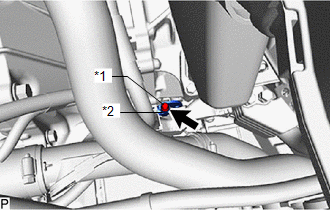
(c) Depress the clutch pedal 5 times, and then loosen the bleeder plug while the pedal is depressed.*1
(d) When fluid no longer comes out, tighten the bleeder plug, and then release the clutch pedal.*2
(e) Repeat steps *1 and *2 until all the air in the brake fluid is completely bled out.
NOTICE:
Add brake fluid to keep the level between the MIN and MAX lines of the reservoir while replacing the brake fluid.
(f) Check that all the air has been bled from the clutch line.
(g) Tighten the bleeder plug.
Torque:
8.4 N·m {86 kgf·cm, 74 in·lbf}
(h) Depress the clutch pedal 10 times or more and confirm its operation.
NOTICE:
This must be performed before the engine is started.
(i) Install the bleeder plug cap.
5. INSPECT FOR BRAKE FLUID LEAK
6. INSPECT BRAKE FLUID LEVEL IN RESERVOIR
Click here

7. INSTALL BRAKE MASTER CYLINDER RESERVOIR FILLER CAP ASSEMBLY
Click here

8. INSTALL CENTER COWL TOP VENTILATOR LOUVER
Click here

 Problem Symptoms Table
PROBLEM SYMPTOMS TABLE HINT: Use the table below to help determine the cause of problem symptoms. If multiple suspected areas are listed, the potential causes of the symptoms are listed in order of probability in the "Suspected Area" column of the table...
 Clutch Unit
..
Other information:
Toyota Yaris XP210 (2020-2026) Owner's Manual: Tire Rotation
During rotation, inspect them for correct balance. Also, inspect them for uneven wear and damage. Abnormal wear is usually caused by one or a combination of the following: Incorrect tire pressure Improper wheel alignment Out-of-balance wheel Severe braking After rotation, inflate all tire pressures to specification and inspect the lug nuts for tightness...
Toyota Yaris XP210 (2020-2026) Owner's Manual: Driving In Flooded Area
WARNING Dry off brakes that have become wet by driving slowly, releasing the accelerator pedal and lightly applying the brakes several times until the brake performance returns to normal Driving with wet brakes is dangerous. Increased stopping distance or the vehicle pulling to one side when braking could result in a serious accident...
Categories
- Manuals Home
- Toyota Yaris Owners Manual
- Toyota Yaris Service Manual
- How to connect USB port/Auxiliary jack
- Engine Start Function When Key Battery is Dead
- G16e-gts (engine Mechanical)
- New on site
- Most important about car
Front Seat Belt Pretensioners
The front seat belt pretensioners are designed to deploy in moderate or severe frontal, near frontal collisions.
In addition, the pretensioners operate when a side collision or a rollover accident is detected. The pretensioners operate differently depending on what types of air bags are equipped. For more details about the seat belt pretensioner operation, refer to the SRS Air Bag Deployment Criteria.