Toyota Yaris: Sfi System / Barometric Pressure - Turbocharger/Supercharger Inlet Pressure Correlation Bank 1 Signal Compare Failure (P006D62)
DESCRIPTION
The E.F.I. vacuum sensor assembly is installed upstream of the turbocharger compressor and measures the air inlet duct internal pressure with a built-in sensor.
At ignition switch to ON or during idling, the E.F.I. vacuum sensor assembly and the atmospheric pressure sensor built into the ECM are at atmospheric pressure and their output match.
| DTC No. | Detection Item | DTC Detection Condition | Trouble Area | MIL | Note |
|---|---|---|---|---|---|
| P006D62 | Barometric Pressure - Turbocharger/Supercharger Inlet Pressure Correlation Bank 1 Signal Compare Failure | Either of the following conditions is met (1 trip detection logic):
|
| - | SAE: P006D |
MONITOR DESCRIPTION
At ignition switch to ON or during idling, if the difference in atmospheric pressure values is the threshold or greater when the output values from the E.F.I. vacuum sensor assembly and the atmospheric pressure sensor built into the ECM are compared, or if the deviation between the air cleaner pressure loss calculated from the atmospheric pressure and E.F.I. vacuum sensor assembly and the air cleaner pressure loss estimated from the mass air flow meter sub-assembly is at the threshold or higher while driving (example: when the intake air volume is 40 gm/sec, the value obtained by subtracting the atmospheric pressure from the E.F.I. vacuum sensor assembly value is larger than 7.5 kPa [1.09 psi]or less than -9.2 kPa [-1.33 psi]), the ECM stores a DTC.
MONITOR STRATEGY
| Frequency of Operation | Continuous |
CONFIRMATION DRIVING PATTERN
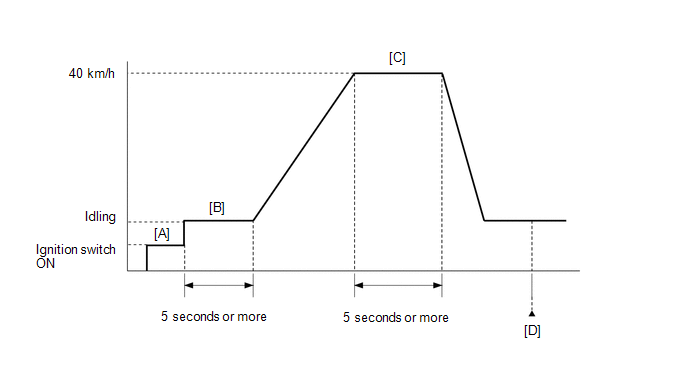
- Connect the GTS to the DLC3.
- Turn the ignition switch to ON and turn the GTS on.
- Clear the DTCs (even if no DTCs are stored, perform the clear DTC procedure).
- Turn the ignition switch off and wait for at least 30 seconds.
- Turn the ignition switch to ON and turn the GTS on [A].
- Start the engine and wait 5 seconds or more [B].
- Drive the vehicle at 40 km/h (25 mph) for 5 seconds or more [C].
- Enter the following menus: Powertrain / Engine / Trouble Codes [D].
-
Read the pending DTCs.
HINT:
- If a pending DTC is output, the system is malfunctioning.
- If a pending DTC is not output, perform the following procedure.
- Enter the following menus: Powertrain / Engine / Utility / All Readiness.
- Input the DTC: P006D62.
-
Check the DTC judgment result.
GTS Display
Description
NORMAL
- DTC judgment completed
- System normal
ABNORMAL
- DTC judgment completed
- System abnormal
INCOMPLETE
- DTC judgment not completed
- Perform driving pattern after confirming DTC enabling conditions
HINT:
- If the judgment result shows NORMAL, the system is normal.
- If the judgment result shows ABNORMAL, the system has a malfunction.
WIRING DIAGRAM
Refer to DTC P010012 for the mass air flow meter sub-assembly circuit.
Click here

Refer to DTC P012A11 for the E.F.I. vacuum sensor assembly circuit.
Click here

CAUTION / NOTICE / HINT
HINT:
Read Freeze Frame Data using the GTS. The ECM records vehicle and driving condition information as Freeze Frame Data the moment a DTC is stored. When troubleshooting, Freeze Frame Data can help determine if the vehicle was moving or stationary, if the engine was warmed up or not, if the air fuel ratio was lean or rich, and other data from the time the malfunction occurred.
PROCEDURE
| 1. | CHECK ANY OTHER DTCS OUTPUT (IN ADDITION TO DTC P006D62) |
(a) Read the DTCs.
Powertrain > Engine > Trouble Codes| Result | Proceed to |
|---|---|
| P006D62 is output | A |
| P006D62 and other DTCs are output | B |
HINT:
If any DTCs other than P006D62 are output, troubleshoot those DTCs first.
| B |
 | GO TO DTC CHART |
|

| 2. | READ VALUE USING GTS (TURBOCHARGER/SUPERCHARGER INLET PRESSURE BANK1 AND ATMOSPHERIC PRESSURE) |
(a) Enter the following menus.
Powertrain > Engine > Data List| Tester Display |
|---|
| Atmospheric Pressure |
| Turbocharger/Supercharger Inlet Pressure Bank1 |
(b) Compare Turbocharger/Supercharger Inlet Pressure Bank1 and Atmospheric Pressure in the Data List.
| Result | Proceed to |
|---|---|
| Difference between Turbocharger/Supercharger Inlet Pressure Bank1 and Atmospheric Pressure in the Data List exceeds 7.1 kPa [1.03 psi] | A |
| Other than above | B |
| B |
 | GO TO STEP 7 |
|

| 3. | READ VALUE USING GTS (ATMOSPHERIC PRESSURE) |
(a) Enter the following menus.
Powertrain > Engine > Data List| Tester Display |
|---|
| Atmospheric Pressure |
(b) Using the table, read the normal atmospheric pressure value for the applicable altitude and temperature.
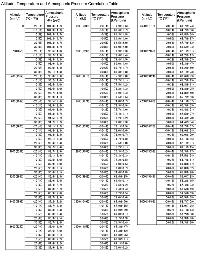
HINT:
- Standard atmospheric pressure is approximately 101 kPa(abs) [14.65 psi(abs)].
- For every 100 m (328 ft.) increase in altitude, atmospheric pressure drops by approximately 1 kPa [0.15 psi]. This varies by weather.
(c) Compare the Atmospheric pressure value in the Data List with the normal atmospheric value from the table.
| Result | Proceed to |
|---|---|
| Other than the following | A |
| Difference between Atmospheric Pressure in the Data List and normal atmospheric pressure value is 10 kPa (1.45 psi) or more. | B |
| B |
 | REPLACE ECM |
|

| 4. | CLEAR DTC |
(a) Clear the DTCs.
Powertrain > Engine > Clear DTCs(b) Turn the ignition switch off and wait for at least 30 seconds.
|

| 5. | READ OUTPUT DTC |
(a) Remove the E.F.I. vacuum sensor assembly, switch bank 1, and then install the E.F.I. vacuum sensor assembly.
(b) Drive the vehicle in accordance with the driving pattern described in Confirmation Driving Pattern.
(c) Read the DTCs.
Powertrain > Engine > Trouble Codes| Result | Proceed to |
|---|---|
| A bank DTC different from the one shown in step 1 is output | A |
| Other than above | B |
| A |
 | REPLACE E.F.I. VACUUM SENSOR ASSEMBLY |
|

| 6. | CHECK HARNESS AND CONNECTOR (E.F.I. VACUUM SENSOR ASSEMBLY - ECM) |
(a) Disconnect the E.F.I. vacuum sensor assembly connector.
(b) Disconnect the ECM connector.
(c) Measure the resistance according to the value(s) in the table below.
Standard Resistance:
| Tester Connection | Condition | Specified Condition |
|---|---|---|
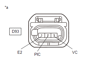
| D93-3(VC) - D104-82(VCPC) | Always | Below 1 Ω |
| D93-2(PIC) - D104-105(PIC) | Always | Below 1 Ω |
| D93-1(E2) - D104-81(EPIC) | Always | Below 1 Ω |
| D93-3(VC) or D104-82(VCPC) - Body ground and other terminals | Always | 10 kΩ or higher |
| D93-2(PIC) or D104-105(PIC) - Body ground and other terminals | Always | 10 kΩ or higher |
| OK |
 | REPLACE ECM |
| NG |
 | REPAIR OR REPLACE HARNESS OR CONNECTOR |
| 7. | CHECK INTAKE SYSTEM |
(a) Check that there is no air suction or blockage at any points in the intake system.
Click here

OK:
No air suction or blockage.
HINT:
Perform "Inspection After Repair" after repairing or replacing the intake system.
Click here

| NG |
 | REPAIR OR REPLACE INTAKE SYSTEM |
|

| 8. | INSPECT MASS AIR FLOW METER SUB-ASSEMBLY |
Click here

| NG |
 | GO TO STEP 14 |
|

| 9. | INSPECT E.F.I. VACUUM SENSOR ASSEMBLY |
Click here

| NG |
 | GO TO STEP 12 |
|

| 10. | CLEAR DTC |
(a) Clear the DTCs.
Powertrain > Engine > Clear DTCs(b) Turn the ignition switch off and wait for at least 30 seconds.
|

| 11. | CHECK WHETHER DTC OUTPUT RECURS (DTC P006D62) |
(a) Drive the vehicle in accordance with the driving pattern described in Confirmation Driving Pattern.
(b) Enter the following menus.
Powertrain > Engine > Utility| Tester Display |
|---|
| All Readiness |
(c) Input the DTC: P006D62.
(d) Check the DTC judgment result.
| Result | Proceed to |
|---|---|
| NORMAL (DTCs are not output) | A |
| ABNORMAL (P006D62 is output) | B |
| A |
 | END |
| B |
 | REPLACE ECM |
| 12. | CHECK HARNESS AND CONNECTOR |
(a) Disconnect the E.F.I. vacuum sensor assembly connector.
(b) Turn the ignition switch to ON.
| (c) Measure the voltage according to the value(s) in the table below. Standard Voltage:
|
|
(d) Turn the ignition switch off and wait for at least 30 seconds.
(e) Measure the resistance according to the value(s) in the table below.
Standard Resistance:
| Tester Connection | Condition | Specified Condition |
|---|---|---|
| D93-3(VC) - D93-2(PIC) | Ignition switch off | 171 to 189 kΩ |
| D93-1(E2) - Body ground | Always | Below 1 Ω |
| OK |
 | REPLACE E.F.I. VACUUM SENSOR ASSEMBLY |
|

| 13. | CHECK HARNESS AND CONNECTOR (E.F.I. VACUUM SENSOR ASSEMBLY - ECM) |
(a) Disconnect the E.F.I. vacuum sensor assembly connector.
(b) Disconnect the ECM connector.
(c) Measure the resistance according to the value(s) in the table below.
Standard Resistance:
| Tester Connection | Condition | Specified Condition |
|---|---|---|
| D93-3(VC) - D104-82(VCPC) | Always | Below 1 Ω |
| D93-2(PIC) - D104-105(PIC) | Always | Below 1 Ω |
| D93-1(E2) - D104-81(EPIC) | Always | Below 1 Ω |
| D93-3(VC) or D104-82(VCPC) - Body ground and other terminals | Always | 10 kΩ or higher |
| D93-2(PIC) or D104-105(PIC) - Body ground and other terminals | Always | 10 kΩ or higher |
| OK |
 | REPLACE ECM |
| NG |
 | REPAIR OR REPLACE HARNESS OR CONNECTOR |
| 14. | CHECK HARNESS AND CONNECTOR |
(a) Disconnect the mass air flow meter sub-assembly connector.
(b) Turn the ignition switch to ON.
| (c) Measure the voltage according to the value(s) in the table below. Standard Voltage:
|
|
(d) Turn the ignition switch off and wait for at least 30 seconds.
(e) Measure the resistance according to the value(s) in the table below.
Standard Resistance:
| Tester Connection | Condition | Specified Condition |
|---|---|---|
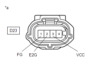
| D23-3(VCC) - D23-1(FG) | Ignition switch off | 2.09 to 2.31 kΩ |
| D23-2(E2G) - Body ground | Always | Below 1 Ω |
HINT:
Perform "Inspection After Repair" after replacing the mass air flow meter sub-assembly.
Click here

| OK |
 | REPLACE MASS AIR FLOW METER SUB-ASSEMBLY |
|

| 15. | CHECK HARNESS AND CONNECTOR (MASS AIR FLOW METER SUB-ASSEMBLY - ECM) |
(a) Disconnect the mass air flow meter sub-assembly connector.
(b) Disconnect the ECM connector.
(c) Measure the resistance according to the value(s) in the table below.
Standard Resistance:
| Tester Connection | Condition | Specified Condition |
|---|---|---|
| D23-3(VCC) - D104-84(VCVG) | Always | Below 1 Ω |
| D23-1(FG) - D104-107(VG) | Always | Below 1 Ω |
| D23-2(E2G) - D104-83(E2G) | Always | Below 1 Ω |
| D23-3(VCC) or D104-84(VCVG) - Body ground and other terminals | Always | 10 kΩ or higher |
| D23-1(FG) or D104-107(VG) - Body ground and other terminals | Always | 10 kΩ or higher |
| OK |
 | REPLACE ECM |
| NG |
 | REPAIR OR REPLACE HARNESS OR CONNECTOR |
 HO2S Heater Control Circuit Bank 1 Sensor 2 Circuit Short to Battery (P003612,P003613,P102A9E)
DESCRIPTION The air fuel ratio sensor (sensor 2) generates current that corresponds to the actual air fuel ratio. This sensor current is used to provide the ECM with feedback so that it can control the air fuel ratio...
 Charge Air Cooler Temperature Sensor Bank 1 Circuit Short to Ground (P007A11)
DESCRIPTION
The intake air temperature sensor, built into the No. 2 turbo pressure sensor, monitors the intake air temperature. The intake air temperature sensor has a built-in thermistor with a resistance that varies according to the temperature of the intake air...
Other information:
Toyota Yaris XP210 (2020-2025) Owner's Manual: Activation/Deactivation
To activate the system, press the ON switch. The cruise main indication (white) is displayed. To deactivate the system, press the OFF/CAN switch. The cruise main indication (white) turns off. When the ignition is switched OFF, the system status before it was turned off is maintained...
Toyota Yaris XP210 (2020-2025) Reapir and Service Manual: Intelligent Manual Transmission Switch
ComponentsCOMPONENTS ILLUSTRATION *1 INTELLIGENT MANUAL TRANSMISSION SWITCH (COMBINATION SWITCH ASSEMBLY) - - InspectionINSPECTION PROCEDURE 1. INSPECT INTELLIGENT MANUAL TRANSMISSION SWITCH (COMBINATION SWITCH ASSEMBLY) (a) Check the resistance...
Categories
- Manuals Home
- Toyota Yaris Owners Manual
- Toyota Yaris Service Manual
- Auto Lock/Unlock Function
- Opening and Closing the Liftgate/Trunk Lid
- How to use USB mode
- New on site
- Most important about car
Liftgate/Trunk Lid
WARNING
Never allow a person to ride in the luggage compartment/trunk
Allowing a person to ride in the luggage compartment/trunk is dangerous. The person in the luggage compartment/trunk could be seriously injured or killed during sudden braking or a collision.
Do not drive with the liftgate/trunk lid open