Toyota Yaris: Lighting (ext) / Back-up Light Assembly
Components
COMPONENTS
ILLUSTRATION
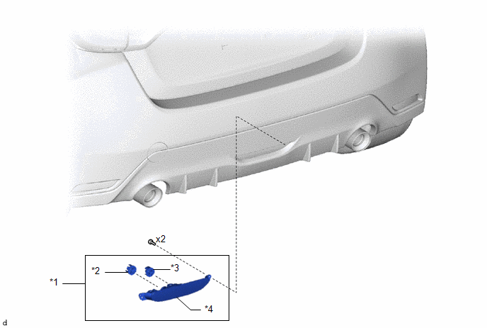
| *1 | BACK-UP LIGHT ASSEMBLY | *2 | BACK-UP LIGHT LED |
| *3 | REAR FOG LIGHT LED | *4 | BACK-UP LIGHT LENS AND BODY |
Removal
REMOVAL
PROCEDURE
1. REMOVE BACK-UP LIGHT ASSEMBLY
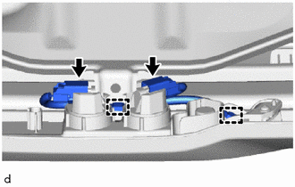
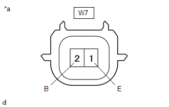
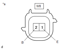
| (a) Disengage the clamps and disconnect the 2 connectors. |
|
| (b) Remove the 2 screws. |
|
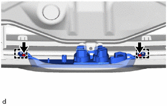
(c) Disengage the guides to remove the back-up light assembly.
Disassembly
DISASSEMBLY
PROCEDURE
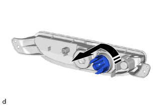
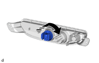
1. REMOVE REAR FOG LIGHT LED
(a) Remove the rear fog light LED as shown in the illustration.
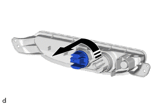
.png) | Remove in this Direction |
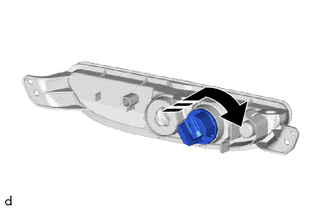
2. REMOVE BACK-UP LIGHT LED
(a) Remove the back-up light LED as shown in the illustration.
|
| Remove in this Direction |
Inspection
INSPECTION
PROCEDURE
1. INSPECT BACK-UP LIGHT LED
(a) Check that the back-up light LED.
| (1) Apply auxiliary battery voltage to the back-up light LED and check that the light comes on. OK:
If the result is not as specified, replace the back-up light LED. |
|
2. INSPECT REAR FOG LIGHT LED
(a) Check that the rear fog light LED.
| (1) Apply auxiliary battery voltage to the rear fog light LED and check that the light comes on. OK:
If the result is not as specified, replace the rear fog light LED. |
|
Reassembly
REASSEMBLY
PROCEDURE
1. INSTALL BACK-UP LIGHT LED
(a) Install the back-up light LED as shown in the illustration.
.png) | Install in this Direction |
2. INSTALL REAR FOG LIGHT LED
(a) Install the rear fog light LED as shown in the illustration.
|
| Install in this Direction |
Installation
INSTALLATION
PROCEDURE
1. INSTALL BACK-UP LIGHT ASSEMBLY
| (a) Engage the guides to install the back-up light assembly. |
|
.png)
(b) Install the 2 screws.
| (c) Connect the 2 connectors and engage the clamps. |
|
.png)
 Installation
INSTALLATION PROCEDURE 1. INSTALL AUTOMATIC LIGHT CONTROL SENSOR (a) Engage the claws to install the automatic light control sensor.
2...

Other information:
Toyota Yaris XP210 (2020-2026) Reapir and Service Manual: Front Brake Flexible Hose
ComponentsCOMPONENTS ILLUSTRATION *1 FRONT FLEXIBLE HOSE *2 GASKET *3 BRAKE LINE *4 FRONT SPEED SENSOR *5 UNION BOLT - - Tightening torque for "Major areas involving basic vehicle performance such as moving/turning/stopping": N*m (kgf*cm, ft...
Toyota Yaris XP210 (2020-2026) Reapir and Service Manual: Removal
REMOVAL CAUTION / NOTICE / HINT CAUTION: Be sure to read Precaution thoroughly before servicing. Click here Wear protective gloves. Sharp areas on the parts may injure your hands. HINT: When the cable is disconnected / reconnected to the auxiliary battery terminal, systems temporarily stop operating...
Categories
- Manuals Home
- Toyota Yaris Owners Manual
- Toyota Yaris Service Manual
- Immobilizer System
- Power Integration No.1 System Missing Message (B235287,B235587,B235787-B235987)
- Engine Start Function When Key Battery is Dead
- New on site
- Most important about car
Fuel Gauge
The fuel gauge shows approximately how much fuel is remaining in the tank when the ignition is switched ON. We recommend keeping the tank over 1/4 full.
