Toyota Yaris: Door / Hatch / Back Door Opener Switch
Components
COMPONENTS
ILLUSTRATION
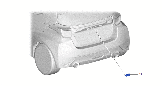
| *1 | BACK DOOR OPENER SWITCH ASSEMBLY | - | - |
Removal
REMOVAL
PROCEDURE
1. REMOVE BACK DOOR OUTSIDE GARNISH SUB-ASSEMBLY
Click here
.gif)
2. REMOVE BACK DOOR OPENER SWITCH ASSEMBLY
(a) Disconnect the connector.
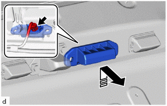
 | Remove in this Direction |
(b) Remove the back door opener switch assembly as shown in the illustration.
Inspection
INSPECTION
PROCEDURE
1. INSPECT BACK DOOR OPENER SWITCH ASSEMBLY (w/ Entry and Start System)
(a) Check the operation of the back door opener switch.
| (1) Measure the resistance according to the value(s) in the table below. Standard Resistance:
If the result is not as specified, replace the back door opener switch assembly. |
|
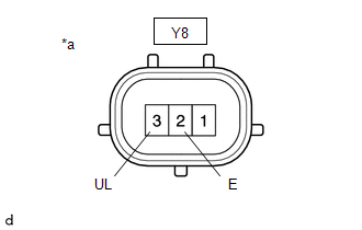
(b) Check the operation of the back door lock switch.
| (1) Measure the resistance according to the value(s) in the table below. Standard Resistance:
If the result is not as specified, replace the back door opener switch assembly. |
|
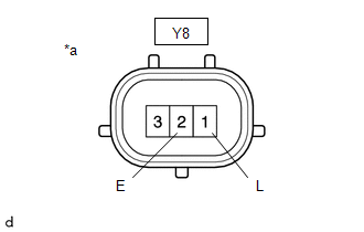
2. INSPECT BACK DOOR OPENER SWITCH ASSEMBLY (w/o Entry and Start System)
(a) Check the operation of the back door opener switch.
| (1) Measure the resistance according to the value(s) in the table below. Standard Resistance:
If the result is not as specified, replace the back door opener switch assembly. |
|
 Reassembly
REASSEMBLY PROCEDURE 1. INSTALL BACK DOOR DUST PROOF SEAL (a) Engage the claw to install 3 new back door dust proof seals.
2. INSTALL NO...
 Back Door Weatherstrip
ComponentsCOMPONENTS ILLUSTRATION
*1 BACK DOOR WEATHERSTRIP - - ● Non-reusable part - - RemovalREMOVAL PROCEDURE 1. REMOVE BACK DOOR WEATHERSTRIP (a) Remove the back door weatherstrip...
Other information:
Toyota Yaris XP210 (2020-2026) Owner's Manual: Height Adjustment
Adjust the head restraint so that the center is even with the top of the passenger’s ears. To raise a head restraint, pull it up to the desired position. To lower the head restraint, press the stop-catch release, then push the head restraint down...
Toyota Yaris XP210 (2020-2026) Owner's Manual: Flashing the Headlights
OFF FlashingTo flash the headlights, pull the lever fully towards you (the headlight switch does not need to be on). The headlight high-beam indicator light in the combination meter illuminates simultaneously. The lever will return to the normal position when released...
Categories
- Manuals Home
- Toyota Yaris Owners Manual
- Toyota Yaris Service Manual
- Adjustment
- Maintenance
- Auto Lock/Unlock Function
- New on site
- Most important about car
Keys

To use the auxiliary key, press the knob and pull out the auxiliary key from the smart key.
