Toyota Yaris: Noise Filter / On-vehicle Inspection
ON-VEHICLE INSPECTION
PROCEDURE
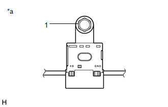
1. INSPECT RADIO SETTING CONDENSER
(a) With the radio setting condenser installed, check that there is no looseness or other abnormalities.
| (b) Measure the resistance of the radio setting condenser according to the value(s) in the table below. Standard Resistance:
|
|
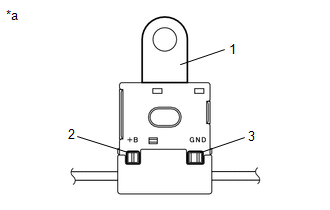
(c) Remove the bolt.
(d) Disengage the clamp and disconnect the radio setting condenser with wire harness from the vehicle body.
| (e) Measure the resistance and voltage of the radio setting condenser according to the value(s) in the table below. Standard Resistance:
Standard Voltage:
|
|
 Components
C..
 Removal
REMOVAL PROCEDURE 1. REMOVE DECK TRIM SIDE PANEL ASSEMBLY LH Click here
2. REMOVE RADIO SETTING CONDENSER NOTICE: When the terminal cover is removed, the radio setting condenser must be replaced because the terminal cover and condenser are supplied as a set...
Other information:
Toyota Yaris XP210 (2020-2026) Reapir and Service Manual: Left Rear Wheel Speed Sensor Circuit Intermittent (C050C1F)
DESCRIPTION The speed sensor detects wheel speed and sends the appropriate signals to the skid control ECU (brake actuator assembly). These signals are used for brake control. Speed sensor rotors have rows of alternating N and S magnetic poles, and their magnetic fields change when the rotors turn...
Toyota Yaris XP210 (2020-2026) Reapir and Service Manual: Installation
INSTALLATION PROCEDURE 1. INSTALL ROOF HEADLINING (a) Tilt the roof headlining diagonally and insert it into the cabin through the passenger side door as shown in the illustration. Insert in this Direction NOTICE: Check that the corners of the roof headlining are not folded, twisted or otherwise deformed and that none of the mounted parts have fallen off...
Categories
- Manuals Home
- Toyota Yaris Owners Manual
- Toyota Yaris Service Manual
- Brake System Control Module "A" System Voltage System Voltage Low (C137BA2)
- Engine Start Function When Key Battery is Dead
- Key Battery Replacement
- New on site
- Most important about car
Refueling
Before refueling, close all the doors, windows, and the liftgate/trunk lid, and switch the ignition OFF.
To open the fuel-filler lid, pull the remote fuel-filler lid release.
