Toyota Yaris: Air Conditioning System / Air Vent cannot be Switched
DESCRIPTION
If the air outlet mode does not change even though the air outlet display changes, the following factors may be the cause.
| Symptom | Factor |
|---|---|
| Air outlet mode cannot be changed
|
|
PROCEDURE
| 1. | CHECK NO. 1 AIR CONDITIONING RADIATOR DAMPER SERVO SUB-ASSEMBLY |
(a) Check that the No. 1 air conditioning radiator damper servo sub-assembly is installed correctly.
Click here

OK:
The No. 1 air conditioning radiator damper servo sub-assembly is installed correctly.
| NG |
 | INSTALL NO. 1 AIR CONDITIONING RADIATOR DAMPER SERVO SUB-ASSEMBLY |
|
| 2. | SERVO MOTOR INITIALIZATION |
Click here

|
| 3. | CHECK FOR DTC |
(a) Check for DTCs.
Body Electrical > Air Conditioner > Trouble Codes| Result | Proceed to |
|---|---|
| B140287 and B14037F is not output | A |
| B140287 is output | B |
| B14037F is output | C |
| A |
 | REPAIR OR REPLACE AIR CONDITIONING RADIATOR ASSEMBLY |
| B |
 | GO TO DTC B140287 |
| C |
 | GO TO DTC B14037F |
 No Cool Air Comes Out
DESCRIPTION If warm air blows from the registers regardless of the temperature setting of the air conditioning system, the following factors may be the cause...
 Air Vent Temperature does not Change and Right Vent is Different from Left and Vice Versa (Same Left/Right Temperature Setting)
DESCRIPTION If the temperature of the air that blows from the left and right front registers differs, even though the same temperature is set for both sides, the following factors may be the cause...
Other information:
Toyota Yaris XP210 (2020-2026) Reapir and Service Manual: Steering Angle Sensor Communication Stop Mode
DESCRIPTION Detection Item Symptom Trouble Area Steering Angle Sensor Communication Stop Mode Communication stop for "Spiral cable (Steering Angle Sensor)" is indicated on the "Communication Bus Check" screen of the GTS. Click here Steering sensor branch line or connector Power source circuit of steering sensor Steering sensor ground circuit Steering sensor WIRING DIAGRAM CAUTION / NOTICE / HINT CAUTION: When performing the confirmation driving pattern, obey all speed limits and traffic laws...
Toyota Yaris XP210 (2020-2026) Reapir and Service Manual: Components
C..
Categories
- Manuals Home
- Toyota Yaris Owners Manual
- Toyota Yaris Service Manual
- Engine Start Function When Key Battery is Dead
- Power Integration No.1 System Missing Message (B235287,B235587,B235787-B235987)
- How to connect USB port/Auxiliary jack
- New on site
- Most important about car
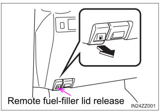
Refueling
Before refueling, close all the doors, windows, and the liftgate/trunk lid, and switch the ignition OFF.
To open the fuel-filler lid, pull the remote fuel-filler lid release.


