Toyota Yaris: Sfi System / Air Intake Control Valve Circuit Short to Ground or Open (P166014)
DESCRIPTION
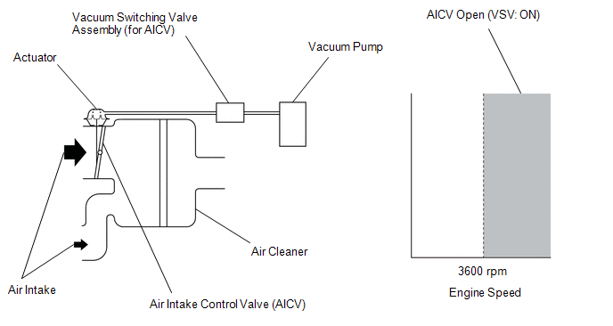
The air cleaner is equipped with two inlets, one of which is opened or closed by the Air Intake Control Valve (AICV). This system reduces intake noise and increases engine power at low-to-high engine speed range. When the engine is operating in the low-to-mid speed range, this control operates the AICV to close one of the air cleaner inlets. When the engine speed is more than 3600 rpm, the ECM activates VSV and opens the AICV.
| DTC No. | Detection Item | DTC Detection Condition | Trouble Area | MIL | Note |
|---|---|---|---|---|---|
| P166014 | Air Intake Control Valve Circuit Short to Ground or Open | Voltage of terminal air intake control valve of the ECM is low when the VSV is not operating for 3 seconds or more (1 trip detection logic). |
| - | SAE: P1660 |
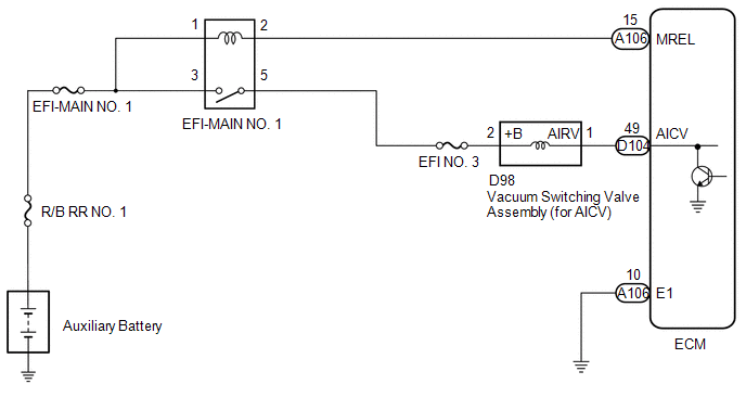
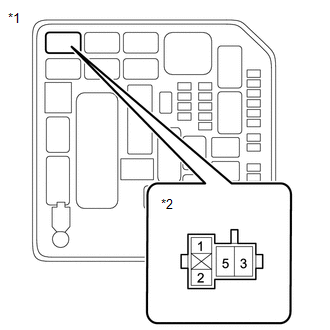
WIRING DIAGRAM
CAUTION / NOTICE / HINT
NOTICE:
Inspect the fuses for circuits related to this system before performing the following procedure.
HINT:
Read Freeze Frame Data using the GTS. The ECM records vehicle and driving condition information as Freeze Frame Data the moment a DTC is stored. When troubleshooting, Freeze Frame Data can help determine if the vehicle was moving or stationary, if the engine was warmed up or not, if the air fuel ratio was lean or rich, and other data from the time the malfunction occurred.
PROCEDURE
| 1. | PERFORM ACTIVE TEST USING GTS (ACTIVATE THE VSV FOR AICS) |
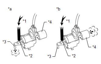
| *1 | Air |
| *2 | Port E |
| *3 | Port F |
| *4 | Air Filter |
| *a | Vacuum Switching Valve is On |
| *b | Vacuum Switching Valve is Off |
(a) Disconnect the vacuum hose (port F) from the vacuum switching valve assembly (for AICV).
(b) Enter the following menus.
Powertrain > Engine > Active Test| Tester Display |
|---|
| Activate the VSV for AICS |
(c) Check the operation of the vacuum switching valve assembly (for AICV) when the vacuum switching valve assembly (for AICV) is operated using the GTS.
Standard:
| GTS Connection | Specified Condition |
|---|---|
| ON | Air from port E flows out through port F |
| OFF | Air from port E flows out through the air filter |
| OK |
 | CHECK FOR INTERMITTENT PROBLEMS |
|

| 2. | INSPECT VACUUM SWITCHING VALVE ASSEMBLY (FOR AICV) |
Click here

| NG |
 | REPLACE VACUUM SWITCHING VALVE ASSEMBLY (FOR AICV) |
|

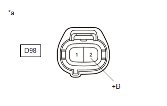
| 3. | CHECK TERMINAL VOLTAGE (POWER SOURCE OF VACUUM SWITCHING VALVE ASSEMBLY (FOR AICV)) |
(a) Disconnect the vacuum switching valve assembly (for AICV) connector.
(b) Turn the ignition switch to ON.
| (c) Measure the voltage according to the value(s) in the table below. Standard Voltage:
|
|
| NG |
 | GO TO STEP 5 |
|

| 4. | CHECK HARNESS AND CONNECTOR (VACUUM SWITCHING VALVE ASSEMBLY (FOR AICV) - ECM) |
(a) Disconnect the vacuum switching valve assembly (for AICV) connector.
(b) Disconnect the ECM connector.
(c) Measure the resistance according to the value(s) in the table below.
Standard Resistance:
| Tester Connection | Condition | Specified Condition |
|---|---|---|
| D98-1(AIRV) - D104-49(AICV) | Always | Below 1 Ω |
| D98-1(AIRV) or D104-49(AICV) - Body ground | Always | 10 kΩ or higher |
| OK |
 | REPLACE ECM |
| NG |
 | REPAIR OR REPLACE HARNESS OR CONNECTOR |
| 5. | INSPECT EFI-MAIN NO. 1 RELAY |
Click here

| NG |
 | REPLACE EFI-MAIN NO. 1 RELAY |
|

| 6. | CHECK HARNESS AND CONNECTOR (POWER SOURCE OF EFI-MAIN NO.1 RELAY) |
| (a) Remove the EFI-MAIN NO. 1 relay from the No. 1 engine room relay block assembly. |
|
(b) Measure the voltage according to the value(s) in the table below.
Standard Voltage:
| Tester Connection | Condition | Specified Condition |
|---|---|---|
| 3 (EFI-MAIN NO. 3 relay) - Body ground | Always | 11 to 14 V |
| 1 (EFI-MAIN NO. 3 relay) - Body ground | Always | 11 to 14 V |
| NG |
 | REPAIR OR REPLACE HARNESS OR CONNECTOR (AUXILIARY BATTERY - EFI-MAIN NO. 3 RELAY) |
|

| 7. | CHECK HARNESS AND CONNECTOR (EFI-MAIN NO. 1 RELAY - VACUUM SWITCHING VALVE ASSEMBLY (FOR AICV)) |
(a) Remove the EFI-MAIN NO. 1 relay, EFI-MAIN NO. 3 relay and EDU relay from the No. 1 engine room relay block assembly.
HINT:
Remove the EFI-MAIN NO. 3 relay and EDU relay connected between the checked terminals as the coil inside the relay influences the measurement value.
(b) Disconnect the vacuum switching valve assembly (for AICV) connector.
(c) Measure the resistance according to the value(s) in the table below.
Standard Resistance:
| Tester Connection | Condition | Specified Condition |
|---|---|---|
| 5(EFI-MAIN NO.1 relay) - D98-2 (+B) | Always | Below 1 Ω |
| 5(EFI-MAIN NO.1 relay) or D98-2 (+B) - Body ground and other terminals | Always | 10 kΩ or higher |
| OK |
 | CHECK FOR INTERMITTENT PROBLEMS |
| NG |
 | REPAIR OR REPLACE HARNESS OR CONNECTOR |
 Pre-ignition Detected (P137800)
DESCRIPTION If sudden early ignition (pre-ignition) occurs continuously in a short period of time, a DTC is stored. This pre-ignition is a phenomenon inherent in boosted engines...
 Actuator Cut Circuit Stuck Off (P16B09F)
MONITOR DESCRIPTION The ECM monitors the operation of the throttle actuator. When a malfunction is detected in the throttle actuator cut circuit immediately after the ignition switch is turned off, the ECM illuminates the MIL and stores a DTC...
Other information:
Toyota Yaris XP210 (2020-2025) Reapir and Service Manual: On-vehicle Inspection
ON-VEHICLE INSPECTION PROCEDURE 1. CONNECT GTS (a) Connect the GTS to the DLC3 with the engine switch off. (b) Start the engine and run it at idle. (c) Turn the GTS on. (d) Enter the following menus: Chassis / Brake/EPB / Active Test. HINT: Refer to the GTS operator's manual for further details...
Toyota Yaris XP210 (2020-2025) Reapir and Service Manual: Removal
REMOVAL CAUTION / NOTICE / HINT HINT: When the cable is disconnected / reconnected to the auxiliary battery terminal, systems temporarily stop operating. However, each system has a function that completes learning the first time the system is used. Learning completes when vehicle is driven Effect/Inoperative Function When Necessary Procedures are not Performed Necessary Procedures Link Lane tracing assist system Drive the vehicle straight ahead at 35 km/h (22 mph) or more for 5 seconds or more...
Categories
- Manuals Home
- Toyota Yaris Owners Manual
- Toyota Yaris Service Manual
- To Set Speed
- Opening and Closing the Liftgate/Trunk Lid
- Power Integration No.1 System Missing Message (B235287,B235587,B235787-B235987)
- New on site
- Most important about car
Fuel-Filler Lid and Cap
WARNING
When removing the fuel-filler cap, loosen the cap slightly and wait for any hissing to stop, then remove it
Fuel spray is dangerous. Fuel can burn skin and eyes and cause illness if ingested. Fuel spray is released when there is pressure in the fuel tank and the fuel-filler cap is removed too quickly.