Toyota Yaris: Vehicle Stability Control System / VSC OFF Switch Circuit
DESCRIPTION
Operating the VSC OFF switch (combination switch assembly) makes it possible for TRC and/or VSC operation to be prohibited.
Pressing the VSC OFF switch (combination switch assembly) changes to TRC OFF mode, and turns off TRC operation. In addition, a TRC cancel message is displayed on the multi-information display in the combination meter assembly.
While the vehicle is stopped, pressing and holding the VSC OFF switch (combination switch assembly) for 3 seconds or more changes to VSC OFF mode, and turns off both TRC and VSC operation. In addition, a TRC cancel message is displayed on the multi-information display in the combination meter assembly, and the VSC OFF indicator light illuminates.
If the VSC OFF switch is pressed while SPORT or TRACK modes are selected, the mode changes to EXPERT mode, in which control is performed to help prevent the vehicle from spinning during oversteer maneuvers. In addition, the VSC OFF indicator light in the combination meter assembly illuminates, and "EXPERT" is displayed on the multi-information display.
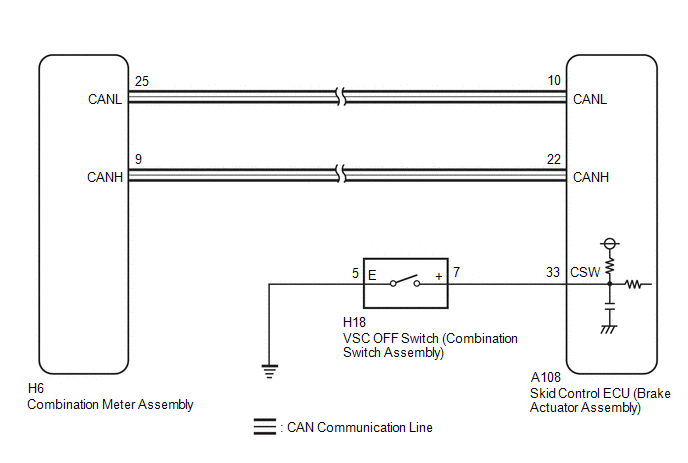
WIRING DIAGRAM
CAUTION / NOTICE / HINT
NOTICE:
After replacing the skid control ECU (brake actuator assembly), perform "Calibration".
Click here

PROCEDURE
| 1. | READ VALUE USING GTS (TRC (TRAC)/VSC OFF MODE) |
(a) Operate the GTS to check the Data List.
Chassis > Brake > Data List| Tester Display | Measurement Item | Range | Normal Condition | Diagnostic Note |
|---|---|---|---|---|
| TRC(TRAC)/VSC OFF Mode | TRC/VSC off mode | Normal mode (TRC(TRAC) ON/VSC ON) / TRC(TRAC) OFF mode (TRC(TRAC) OFF/VSC ON) / VSC expert mode(VSC expert mode MID ON) / VSC OFF mode (TRC(TRAC) OFF/VSC OFF) | Normal mode (TRC(TRAC) ON/VSC ON): Normal mode TRC(TRAC) OFF mode (TRC(TRAC) OFF/VSC ON): TRC off mode VSC expert mode(VSC expert mode MID ON): When TRC and VSC are prohibited during SPORT mode or TRACK mode VSC OFF mode (TRC(TRAC) OFF/VSC OFF): VSC off mode | - |
| Tester Display |
|---|
| TRC(TRAC)/VSC OFF Mode |
(b) Check that the indicator light and mode condition on the GTS change according to VSC OFF switch (combination switch assembly) operation.
Standard:
| Switch Operation | Mode Condition Display | Multi-information Display (TRC OFF Message) | VSC OFF Indicator Light |
|---|---|---|---|
| Not pressed | Normal mode (TRC(TRAC) ON/VSC ON) | Not displayed | Does not come on |
| Pressing the VSC OFF switch (combination switch assembly) | TRC(TRAC) OFF mode (TRC(TRAC) OFF/VSC ON) | Displayed | Does not come on |
| Pressing and holding the VSC OFF switch (combination switch assembly) | VSC OFF mode (TRC(TRAC) OFF/VSC OFF) | Displayed | Comes on |
| Result | Proceed to |
|---|---|
| Indicator light and mode condition display do not change. | A |
| Mode condition display is normal, but indicator light does not change. | B |
| Indicator light and mode condition display are normal. | C |
| B |
 | INSPECT METER / GAUGE SYSTEM |
| C |
 | USE SIMULATION METHOD TO CHECK |
|

| 2. | INSPECT COMBINATION SWITCH ASSEMBLY |
(a) Turn the ignition switch off.
(b) Inspect the VSC OFF switch (combination switch assembly).
Click here

OK:
The VSC OFF switch (combination switch assembly) is normal.
| NG |
 | REPLACE COMBINATION SWITCH ASSEMBLY |
|

| 3. | CHECK HARNESS AND CONNECTOR (BRAKE ACTUATOR ASSEMBLY - COMBINATION SWITCH ASSEMBLY) |
(a) Make sure that there is no looseness at the locking part and the connecting part of the connectors.
OK:
The connector is securely connected.
(b) Disconnect the A108 skid control ECU (brake actuator assembly) connector.
(c) Check both the connector case and the terminals for deformation and corrosion.
OK:
No deformation or corrosion.
(d) Measure the resistance according to the value(s) in the table below.
Standard Resistance:
| Tester Connection | Condition | Specified Condition |
|---|---|---|
| H18-7 (+) - A108-33 (CSW) | Always | Below 1 Ω |
| H18-7 (+) or A108-33 (CSW) - Body ground | Always | 10 kΩ or higher |
| H18-5 (E) - Body ground | 1 minute or more after disconnecting the cable from the negative (-) auxiliary battery terminal | Below 1 Ω |
| OK |
 | REPLACE BRAKE ACTUATOR ASSEMBLY |
| NG |
 | REPAIR OR REPLACE HARNESS OR CONNECTOR |
 Brake Actuator Operation Sound is Loud during Initial Check
CAUTION / NOTICE / HINT NOTICE: After replacing the skid control ECU (brake actuator assembly), perform "Calibration". Click here
PROCEDURE 1. PERFORM ROAD TEST (a) After turning the ignition switch to ON, compare the operating sound of the brake actuator the first time the vehicle speed reaches approximately 25 km/h (16 mph) with a known good vehicle of the same model...
 Vsc Off Switch
ComponentsCOMPONENTS ILLUSTRATION
*1 VSC OFF SWITCH (COMBINATION SWITCH ASSEMBLY) - - InspectionINSPECTION PROCEDURE 1. INSPECT VSC OFF SWITCH (COMBINATION SWITCH ASSEMBLY) (a) Check the resistance...
Categories
- Manuals Home
- Toyota Yaris Owners Manual
- Toyota Yaris Service Manual
- Power Integration No.1 System Missing Message (B235287,B235587,B235787-B235987)
- Engine & Hybrid System
- Diagnostic Trouble Code Chart
- New on site
- Most important about car
Front Seat Belt Pretensioners
The front seat belt pretensioners are designed to deploy in moderate or severe frontal, near frontal collisions.
In addition, the pretensioners operate when a side collision or a rollover accident is detected. The pretensioners operate differently depending on what types of air bags are equipped. For more details about the seat belt pretensioner operation, refer to the SRS Air Bag Deployment Criteria.