Toyota Yaris: Brake Control / Dynamic Control Systems / Vsc Off Switch
Components
COMPONENTS
ILLUSTRATION
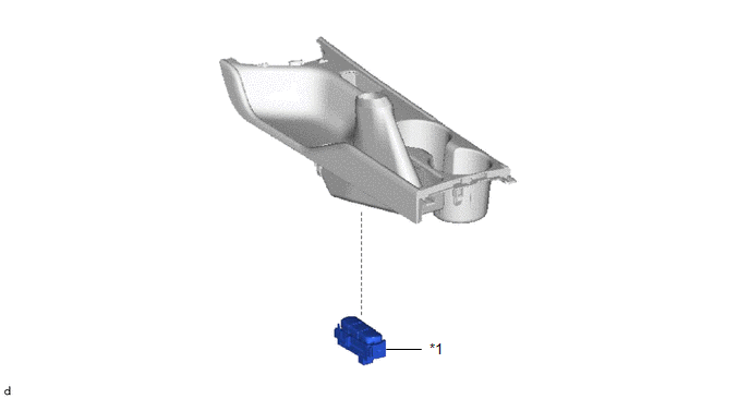
| *1 | VSC OFF SWITCH (COMBINATION SWITCH ASSEMBLY) | - | - |
Inspection
INSPECTION
PROCEDURE
1. INSPECT VSC OFF SWITCH (COMBINATION SWITCH ASSEMBLY)
(a) Check the resistance.
| (1) Measure the resistance according to the value(s) in the table below. Standard Resistance:
If the result is not as specified, replace the VSC OFF Switch (combination switch assembly). |
|
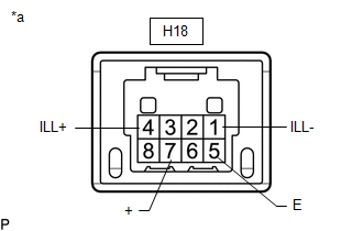
(b) Check the illumination.
(1) Apply auxiliary battery voltage to the VSC OFF Switch (combination switch assembly).
OK:
| Tester Connection | Condition | Specified Condition |
|---|---|---|
| H18-4(ILL+) - H18-1(ILL-) | H18-4(ILL+) - Auxiliary battery positive (+) H18-1(ILL-) - Auxiliary battery negative (-) | The VSC OFF Switch (combination switch assembly) illumination illuminates. |
If the result is not as specified, replace the VSC OFF Switch (combination switch assembly).
 VSC OFF Switch Circuit
DESCRIPTION Operating the VSC OFF switch (combination switch assembly) makes it possible for TRC and/or VSC operation to be prohibited. Pressing the VSC OFF switch (combination switch assembly) changes to TRC OFF mode, and turns off TRC operation...

Other information:
Toyota Yaris XP210 (2020-2026) Reapir and Service Manual: Problem Symptoms Table
PROBLEM SYMPTOMS TABLE NOTICE: Use the table below to help determine the cause of problem symptoms. If multiple suspected areas are listed, the potential causes of the symptoms are listed in order of probability in the "Suspected Area" column of the table...
Toyota Yaris XP210 (2020-2026) Reapir and Service Manual: Removal
REMOVAL CAUTION / NOTICE / HINT The necessary procedures (adjustment, calibration, initialization, or registration) that must be performed after parts are removed and installed, or replaced during vacuum pump assembly removal/installation are shown below...
Categories
- Manuals Home
- Toyota Yaris Owners Manual
- Toyota Yaris Service Manual
- How to use USB mode
- Immobilizer System
- Diagnostic Trouble Code Chart
- New on site
- Most important about car
Keys

To use the auxiliary key, press the knob and pull out the auxiliary key from the smart key.
