Toyota Yaris: Sfi System / Turbocharger / Supercharger Bypass Valve "A" Control Circuit Short to Ground or Open (P003314)
DESCRIPTION
Refer to DTC P003312.
Click here

| DTC No. | Detection Item | DTC Detection Condition | Trouble Area | MIL | Note |
|---|---|---|---|---|---|
| P003314 | Turbocharger / Supercharger Bypass Valve "A" Control Circuit Short to Ground or Open | Open or short in air by-pass valve assembly circuit (1 trip detection logic). |
| - | SAE: P0034 |
MONITOR DESCRIPTION
The ECM monitors the output voltage while the air by-pass valve assembly is operating.
The air by-pass valve assembly turns on and off according to ON/OFF switching of a transistor inside the ECM.
If a continuous mismatch occurs between the ECM transistor state and the output voltage, the ECM determines there is a malfunction in the air by-pass valve assembly circuit and stores a DTC.
CONFIRMATION DRIVING PATTERN
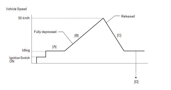
- Connect the GTS to the DLC3.
- Turn the ignition switch to ON and turn the GTS on.
- Clear the DTCs (even if no DTCs are stored, perform the clear DTC procedure).
- Turn the ignition switch off and wait for at least 30 seconds.
- Turn the ignition switch to ON and turn the GTS on.
- Start the engine and warm it up until the engine coolant temperature reaches 75°C (167°F) or higher [A].
-
Accelerate to 50 km/h (31 mph) or more with the accelerator pedal fully depressed [B].
CAUTION:
When performing the confirmation driving pattern, obey all speed limits and traffic laws.
- Quickly release the accelerator pedal from the fully depressed position [C].
- Enter the following menus: Powertrain / Engine / Trouble Codes [D].
-
Read the pending DTCs.
HINT:
- If a pending DTC is output, the system is malfunctioning.
- If a pending DTC is not output, perform the following procedure.
- Enter the following menus: Powertrain / Engine / Utility / All Readiness.
- Input the DTC: P003314.
-
Check the DTC judgment result.
GTS Display
Description
NORMAL
- DTC judgment completed
- System normal
ABNORMAL
- DTC judgment completed
- System abnormal
INCOMPLETE
- DTC judgment not completed
- Perform driving pattern after confirming DTC enabling conditions
HINT:
- If the judgment result shows NORMAL, the system is normal.
- If the judgment result shows ABNORMAL, the system has a malfunction.
- If the judgment result shows INCOMPLETE, perform steps [B] through [D] again.
WIRING DIAGRAM
Refer to DTC P003312.
Click here

CAUTION / NOTICE / HINT
NOTICE:
Inspect the fuses for circuits related to this system before performing the following procedure.
HINT:
Read Freeze Frame Data using the GTS. The ECM records vehicle and driving condition information as Freeze Frame Data the moment a DTC is stored. When troubleshooting, Freeze Frame Data can help determine if the vehicle was moving or stationary, if the engine was warmed up or not, if the air fuel ratio was lean or rich, and other data from the time the malfunction occurred.
PROCEDURE
| 1. | PERFORM ACTIVE TEST USING GTS (ACTIVATE THE AIR BYPASS VALVE) |
(a) Enter the following menus.
Powertrain > Engine > Active Test| Active Test Display |
|---|
| Activate the Air Bypass Valve |
| Data List Display |
|---|
| Air Bypass Valve Control |
(b) According to the display on the GTS, perform the Active Test and check the operation and operation sound of the air by-pass valve.
OK:
| Active Test | Standard |
|---|---|
| ON |
|
| OK |
 | CHECK FOR INTERMITTENT PROBLEMS |
|

| 2. | INSPECT TURBOCHARGER SUB-ASSEMBLY |
Click here

| NG |
 | REPLACE TURBOCHARGER SUB-ASSEMBLY (AIR BY-PASS VALVE MALFUNCTION) |
|

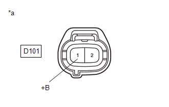
| 3. | CHECK TERMINAL VOLTAGE (POWER SOURCE OF AIR BY-PASS VALVE) |
(a) Disconnect the air by-pass valve connector.
(b) Turn the ignition switch to ON.
| (c) Measure the voltage according to the value(s) in the table below. Standard Voltage:
|
|
| NG |
 | CHECK ECM POWER SOURCE CIRCUIT |
|

| 4. | CHECK HARNESS AND CONNECTOR (AIR BY-PASS VALVE - ECM) |
(a) Disconnect the air by-pass valve connector.
(b) Disconnect the ECM connector.
(c) Measure the resistance according to the value(s) in the table below.
Standard Resistance:
| Tester Connection | Condition | Specified Condition |
|---|---|---|
| D101-2(ABV) - D104-20(ABV) | Always | Below 1 Ω |
| D101-2(ABV) or D104-20(ABV) - Body ground and other terminals | Always | 10 kΩ or higher |
| NG |
 | REPAIR OR REPLACE HARNESS OR CONNECTOR |
|

| 5. | CHECK WHETHER DTC OUTPUT RECURS (DTC P003314) |
(a) Clear the DTCs.
Powertrain > Engine > Clear DTCs(b) Turn the ignition switch off and wait for at least 30 seconds.
(c) Start the engine and warm it up.
(d) Drive the vehicle in accordance with the driving pattern described in the Confirmation Driving Pattern.
(e) Enter the following menus.
Powertrain > Engine > Utility| Tester Display |
|---|
| All Readiness |
(f) Input the DTC: P003314.
(g) Check the DTC judgment result.
| Result | Proceed to |
|---|---|
| NORMAL (DTCs are not output) | A |
| ABNORMAL (P003314 is output) | B |
| A |
 | CHECK FOR INTERMITTENT PROBLEMS |
| B |
 | REPLACE ECM |
 Turbocharger / Supercharger Bypass Valve "A" Control Circuit Short to Battery (P003312)
DESCRIPTION The air by-pass valve assembly is installed in the air outlet duct. It opens and closes in response to drive commands from the ECM. During normal boosting, the air by-pass valve assembly is closed, and when the throttle valve is closed while the boost pressure is applied, the air by-pass valve assembly opens and the excess pressure between the turbocharger and throttle valve is released to prevent the surge phenomenon*...
 HO2S Heater Control Circuit Bank 1 Sensor 2 Circuit Short to Battery (P003612,P003613,P102A9E)
DESCRIPTION The air fuel ratio sensor (sensor 2) generates current that corresponds to the actual air fuel ratio. This sensor current is used to provide the ECM with feedback so that it can control the air fuel ratio...
Other information:
Toyota Yaris XP210 (2020-2025) Reapir and Service Manual: Components
COMPONENTS ILLUSTRATION *1 NO. 1 ENGINE UNDER COVER ASSEMBLY *2 ENGINE UNDER COVER LH *3 ENGINE UNDER COVER RH - - N*m (kgf*cm, ft.*lbf): Specified torque - - ILLUSTRATION *1 FRONT AXLE SHAFT NUT *2 FRONT SPEED SENSOR *3 FRONT FLEXIBLE HOSE *4 STEERING KNUCKLE SEAL *5 COTTER PIN *6 TIE ROD END SUB-ASSEMBLY *7 FRONT STABILIZER LINK ASSEMBLY *8 FRONT LOWER NO...
Toyota Yaris XP210 (2020-2025) Reapir and Service Manual: How To Proceed With Troubleshooting
CAUTION / NOTICE / HINT HINT: Before performing troubleshooting for the front camera system, perform troubleshooting for the pre-collision system. Click here If a pre-collision system related warning message is displayed on the multi-information display, refer to How to Proceed with Troubleshooting for Pre-collision System...
Categories
- Manuals Home
- Toyota Yaris Owners Manual
- Toyota Yaris Service Manual
- Brake System Control Module "A" System Voltage System Voltage Low (C137BA2)
- Engine Start Function When Key Battery is Dead
- Key Battery Replacement
- New on site
- Most important about car
Front Seat Belt Pretensioners
The front seat belt pretensioners are designed to deploy in moderate or severe frontal, near frontal collisions.
In addition, the pretensioners operate when a side collision or a rollover accident is detected. The pretensioners operate differently depending on what types of air bags are equipped. For more details about the seat belt pretensioner operation, refer to the SRS Air Bag Deployment Criteria.