Toyota Yaris: Power Window Control System / Terminals Of Ecu
TERMINALS OF ECU
CHECK MULTIPLEX NETWORK MASTER SWITCH ASSEMBLY

(a) Disconnect the L13 multiplex network master switch assembly connector.
(b) Measure the voltage and resistance according to the value(s) in the table below.
HINT:
Measure the values on the wire harness side with the connector disconnected.
| Terminal No. (Symbol) | Terminal Description | Condition | Specified Condition |
|---|---|---|---|
| L13-11 (B) - L13-12 (GND) | Power supply | Ignition switch off | 11 to 14 V |
| L13-12 (GND) - Body ground | Ground | Always | Below 1 Ω |
(c) Reconnect the L13 multiplex network master switch assembly connector.
(d) Measure the voltage according to the value(s) in the table below.
| Terminal No. (Symbol) | Terminal Description | Condition | Specified Condition |
|---|---|---|---|
| L13-15 (DOWN) - L13-12 (GND) | Power window motor DOWN output | Ignition switch ON, driver door power window regulator switch not pushed or not pulled | 11 to 14 V |
| Ignition switch ON, driver door power window moving, driver door power window regulator switch pushed halfway down (Manual operation) | Below 1 V | ||
| L13-20 (UP) - L13-12 (GND) | Power window motor UP output | Ignition switch ON, driver door power window regulator switch not pushed or not pulled | 11 to 14 V |
| Ignition switch ON, driver door power window moving, driver door power window regulator switch pulled halfway up (Manual operation) | Below 1 V |
CHECK POWER WINDOW REGULATOR SWITCH ASSEMBLY

(a) Disconnect the K13 power window regulator switch assembly connector.
(b) Measure the resistance according to the value(s) in the table below.
HINT:
Measure the values on the wire harness side with the connector disconnected.
| Terminal No. (Symbol) | Terminal Description | Condition | Specified Condition |
|---|---|---|---|
| K13-7 (GND) - Body ground | Ground | Always | Below 1 Ω |
(c) Reconnect the K13 power window regulator switch assembly connector.
(d) Measure the voltage according to the value(s) in the table below.
| Terminal No. (Symbol) | Terminal Description | Condition | Specified Condition |
|---|---|---|---|
| K13-5 (UP) - K13-7 (GND) | Power window motor UP output | Ignition switch ON, power window regulator switch assembly not pushed or not pulled | 11 to 14 V |
| Ignition switch ON, front passenger door power window moving, power window regulator switch assembly pulled halfway up (Manual operation) | Below 1 V | ||
| Ignition switch ON, front passenger door power window fully open | 11 to 14 V | ||
| Ignition switch ON, front passenger door power window moving, power window regulator switch assembly fully pulled up (Auto operation) | Below 1 V | ||
| Ignition switch ON, front passenger door power window fully closed | 11 to 14 V | ||
| K13-4 (DOWN) - K13-7 (GND) | Power window motor DOWN output | Ignition switch ON, power window regulator switch assembly not pushed or not pulled | 11 to 14 V |
| Ignition switch ON, front passenger door power window moving, power window regulator switch assembly pushed halfway down (Manual operation) | Below 1 V | ||
| Ignition switch ON, front passenger door power window fully closed | 11 to 14 V | ||
| Ignition switch ON, front passenger door power window moving, power window regulator switch assembly fully pushed down (Auto operation) | Below 1 V | ||
| Ignition switch ON, front passenger door power window fully open | 11 to 14 V | ||
| K13-8 (AUTO) - K13-7 (GND) | Power window motor AUTO UP output | Ignition switch ON, front passenger door power window fully open | 11 to 14 V |
| Ignition switch ON, front passenger door power window moving, power window regulator switch assembly fully pulled up (Auto operation) | Below 1 V | ||
| Ignition switch ON, front passenger door power window fully closed | 11 to 14 V | ||
| Power window motor AUTO DOWN output | Ignition switch ON, front passenger door power window fully closed | 11 to 14 V | |
| Ignition switch ON, front passenger door power window moving, power window regulator switch assembly fully pushed down (Auto operation) | Below 1 V | ||
| Ignition switch ON, front passenger door power window fully open | 11 to 14 V |
CHECK POWER WINDOW REGULATOR MOTOR ASSEMBLY (for Driver Door)

(a) Disconnect the L7 power window regulator motor assembly (for driver door) connector.
(b) Measure the voltage and resistance according to the value(s) in the table below.
HINT:
Measure the values on the wire harness side with the connector disconnected.
| Terminal No. (Symbol) | Terminal Description | Condition | Specified Condition |
|---|---|---|---|
| L7-1 (GND) - Body ground | Ground | Always | Below 1 Ω |
| L7-2 (B) - Body ground | Power supply | Ignition switch off | 11 to 14 V |
(c) Reconnect the L7 power window regulator motor assembly (for driver door) connector.
(d) Measure the voltage according to the value(s) in the table below.
| Terminal No. (Symbol) | Terminal Description | Condition | Specified Condition |
|---|---|---|---|
| L7-7 (DOWN) - L7-1 (GND) | Power window motor DOWN input | Ignition switch ON, multiplex network master switch assembly (driver door power window regulator switch) not pushed or not pulled | 11 to 14 V |
| Ignition switch ON, driver door power window moving, multiplex network master switch assembly (driver door power window regulator switch) pushed halfway down (Manual operation) | Below 1 V | ||
| Ignition switch ON, driver door power window fully closed | 11 to 14 V | ||
| Ignition switch ON, driver door power window moving, multiplex network master switch assembly (driver door power window regulator switch) fully pushed down (Auto operation) | Below 1 V | ||
| Ignition switch ON, driver door power window fully open | 11 to 14 V | ||
| L7-10 (UP) - L7-1 (GND) | Power window motor UP input | Ignition switch ON, multiplex network master switch assembly (driver door power window regulator switch) not pushed or not pulled | 11 to 14 V |
| Ignition switch ON, driver door power window moving, multiplex network master switch assembly (driver door power window regulator switch) pulled halfway up (Manual operation) | Below 1 V | ||
| Ignition switch ON, multiplex network master switch assembly (driver door power window regulator switch) fully open | 11 to 14 V | ||
| Ignition switch ON, driver door power window moving, multiplex network master switch assembly (driver door power window regulator switch) fully pulled up (Auto operation) | Below 1 V | ||
| Ignition switch ON, driver door power window fully closed | 11 to 14 V |

CHECK POWER WINDOW REGULATOR MOTOR ASSEMBLY (for Front Passenger Door)
(a) Disconnect the K7 power window regulator motor assembly (for front passenger door) connector.
(b) Measure the voltage and resistance according to the value(s) in the table below.
HINT:
Measure the values on the wire harness side with the connector disconnected.
| Terminal No. (Symbol) | Terminal Description | Condition | Specified Condition |
|---|---|---|---|
| K7-1 (GND) - Body ground | Ground | Always | Below 1 Ω |
| K7-2 (B) - Body ground | Power supply | Ignition switch off | 11 to 14 V |
(c) Reconnect the K7 power window regulator motor assembly (for front passenger door) connector.
(d) Measure the voltage according to the value(s) in the table below.
| Terminal No. (Symbol) | Terminal Description | Condition | Specified Condition |
|---|---|---|---|
| K7-4 (AUTO) - K7-1 (GND) | Power window motor AUTO UP input | Ignition switch ON, front passenger door power window fully open | 11 to 14 V |
| Ignition switch ON, front passenger door power window moving, power window regulator switch assembly fully pulled up (Auto operation) | Below 1 V | ||
| Ignition switch ON, front passenger door power window fully closed | 11 to 14 V | ||
| Power window motor AUTO DOWN input | Ignition switch ON, front passenger door power window fully closed | 11 to 14 V | |
| Ignition switch ON, front passenger door power window moving, power window regulator switch assembly fully pushed down (Auto operation) | Below 1 V | ||
| Ignition switch ON, front passenger door power window fully open | 11 to 14 V | ||
| K7-7 (DOWN) - K7-1 (GND) | Power window motor DOWN input | Ignition switch ON, power window regulator switch assembly not pushed or not pulled | 11 to 14 V |
| Ignition switch ON, front passenger door power window moving, power window regulator switch assembly pushed halfway down (Manual operation) | Below 1 V | ||
| Ignition switch ON, front passenger door power window fully closed | 11 to 14 V | ||
| Ignition switch ON, front passenger door power window moving, power window regulator switch assembly fully pushed down (Auto operation) | Below 1 V | ||
| Ignition switch ON, front passenger door power window fully open | 11 to 14 V | ||
| K7-10 (UP) - K7-1 (GND) | Power window motor UP input | Ignition switch ON, power window regulator switch assembly not pushed or not pulled | 11 to 14 V |
| Ignition switch ON, front passenger door power window moving, power window regulator switch assembly pulled halfway up (Manual operation) | Below 1 V | ||
| Ignition switch ON, front passenger door power window fully open | 11 to 14 V | ||
| Ignition switch ON, front passenger door power window moving, power window regulator switch assembly fully pulled up (Auto operation) | Below 1 V | ||
| Ignition switch ON, front passenger door power window fully closed | 11 to 14 V |
CHECK POWER DISTRIBUTION BOX ASSEMBLY AND MAIN BODY ECU (MULTIPLEX NETWORK BODY ECU)
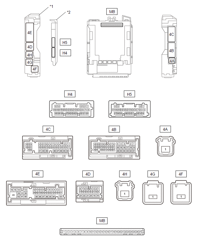
| *1 | Power Distribution Box Assembly | *2 | Main Body ECU (Multiplex Network Body ECU) |
(a) Remove the main body ECU (multiplex network body ECU) from the power distribution box assembly.
Click here
.gif)
(b) Reconnect the power distribution box assembly connectors.
(c) Measure the voltage and resistance according to the value(s) in the table below.
HINT:
Measure the values on the wire harness side with the connectors connected.
| Terminal No. (Symbol) | Terminal Description | Condition | Specified Condition |
|---|---|---|---|
| MB-13 (GND1) - Body ground | Ground | Always | Below 1 Ω |
| MB-26 (BECU) - Body ground | Auxiliary battery power supply | Ignition switch off | 11 to 14 V |
| MB-27 (IGR) - Body ground | IG power supply | Ignition switch ON | 11 to 14 V |
(d) Install the main body ECU (multiplex network body ECU) to the power distribution box assembly.
Click here
(e) Measure the voltage and check for pulses according to the value(s) in the table below.
| Terminal No. (Symbol) | Terminal Description | Condition | Specified Condition |
|---|---|---|---|
| MB-2 (FLCY) - Body ground | Front door courtesy light switch (for LH) input | Front door LH open | Below 1 V |
| Front door LH closed | 4.7 to 5.3 V | ||
| H4-28 (L2) - Body ground | Driver door key-linked lock input | Driver door key cylinder turned to lock | Below 1 V |
| Driver door key cylinder not turned | Pulse generation | ||
| H4-4 (UL3) - Body ground | Driver door key-linked unlock input | Driver door key cylinder turned to unlock | Below 1 V |
| Driver door key cylinder not turned | Pulse generation |
 Problem Symptoms Table
PROBLEM SYMPTOMS TABLE NOTICE: Before replacing the main body ECU (multiplex network body ECU), refer to Service Bulletin. HINT:
Use the table below to help determine the cause of problem symptoms...
 Diagnosis System
DIAGNOSIS SYSTEM DESCRIPTION (a) Power window control system data and Diagnostic Trouble Codes (DTCs) can be read through the vehicle Data Link Connector 3 (DLC3)...
Other information:
Toyota Yaris XP210 (2020-2026) Owner's Manual: Overheating
If the high engine coolant temperature warning light turns on, the vehicle loses power, or you hear a loud knocking or pinging noise, the engine is probably too hot. If the high engine coolant temperature warning light turns on: Drive safely to the side of the road and park off the right-of-way...
Toyota Yaris XP210 (2020-2026) Reapir and Service Manual: Customize Parameters
CUSTOMIZE PARAMETERS CUSTOMIZE WIPER AND WASHER SYSTEM NOTICE: When the customer requests a change in a function, first make sure that the function can be customized. Be sure to make a note of the current settings before customizing. When troubleshooting a function, first make sure that the function is set to the default setting...
Categories
- Manuals Home
- Toyota Yaris Owners Manual
- Toyota Yaris Service Manual
- G16e-gts (engine Mechanical)
- Opening and Closing the Liftgate/Trunk Lid
- Key Battery Replacement
- New on site
- Most important about car
Break-In Period
No special break-in is necessary, but a few precautions in the first 600 miles (1,000 km) may add to the performance, economy, and life of the vehicle.
Do not race the engine. Do not maintain one constant speed, either slow or fast, for a long period of time. Do not drive constantly at full-throttle or high engine rpm for extended periods of time. Avoid unnecessary hard stops. Avoid full-throttle starts.