Toyota Yaris: Smart Key System (for Start Function) / System Malfunction Message is Displayed on the Multi-information Display
SYSTEM DESCRIPTION
If an abnormal operation that may lead to a malfunction of the steering lock ECU (steering lock actuator or upper bracket assembly), or abnormal vehicle speed information is detected by the certification ECU (smart key ECU assembly), a system malfunction message is displayed on the multi-information display.
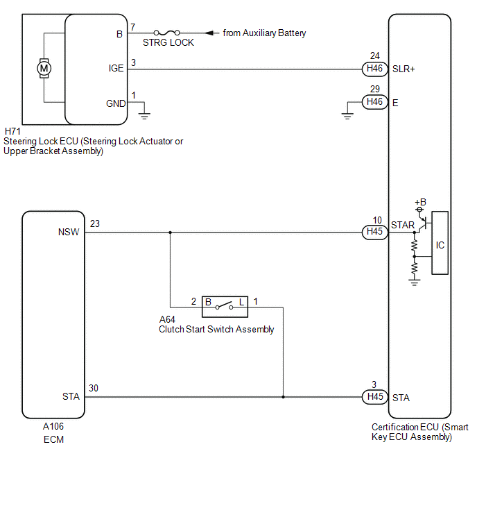
WIRING DIAGRAM
CAUTION / NOTICE / HINT
NOTICE:
- When using the GTS with the ignition switch off, connect the GTS to the DLC3 and turn a courtesy light switch on and off at intervals of 1.5 seconds or less until communication between the GTS and the vehicle begins. Then select the vehicle type under manual mode and enter the following menus: Body Electrical / Smart Key. While using the GTS, periodically turn a courtesy light switch on and off at intervals of 1.5 seconds or less to maintain communication between the GTS and the vehicle.
-
The smart key system (for Start Function) uses the LIN communication system and CAN communication system. Inspect the communication function by following How to Proceed with Troubleshooting. Troubleshoot the smart key system (for Start Function) after confirming that the communication systems are functioning properly.
Click here

-
Before replacing the certification ECU (smart key ECU assembly) or steering lock ECU (steering lock actuator or upper bracket assembly), refer to Registration.
Click here

PROCEDURE
| 1. | CHECK FOR DTC |
(a) Check for DTCs.
Body Electrical > Smart Key > Trouble Codes Body Electrical > Power Source Control > Trouble Codes| Result | Proceed to |
|---|---|
| DTCs are not output | A |
| DTC is output. | B |
| B |
 | GO TO SMART KEY SYSTEM (for Entry Function) (DIAGNOSTIC TROUBLE CODE CHART) |
|

| 2. | READ VALUE USING GTS (SENSOR MALFUNCTION HISTORY) |
(a) Read the Data List according to the display on the GTS.
Body Electrical > Smart Key > Data List| Tester Display | Measurement Item | Range | Normal Condition | Diagnostic Note |
|---|---|---|---|---|
| Sensor Malfunction History | History of malfunction of position sensor in steering lock ECU (steering lock actuator or upper bracket assembly) (DTC B278196 is stored) | OK or NG | OK: History of malfunction for the lock or unlock sensor in the steering lock ECU (steering lock actuator or upper bracket assembly) does not exist. NG: History of both the lock and unlock sensors in the steering lock ECU (steering lock actuator or upper bracket assembly) being on exists. (Under normal operation, neither sensor is on.) | When NG is displayed, either the position sensor in the steering lock ECU (steering lock actuator or upper bracket assembly) or the assembly itself may be malfunctioning. |
| Tester Display |
|---|
| Sensor Malfunction History |
OK:
OK is displayed on the GTS.
| NG |
 | REPLACE STEERING LOCK ECU (STEERING LOCK ACTUATOR OR UPPER BRACKET ASSEMBLY) |
|

| 3. | READ VALUE USING GTS (NEUTRAL SWITCH / CLUTCH SWITCH) |
(a) Read the Data List according to the display on the GTS.
Body Electrical > Power Source Control > Data List| Tester Display | Measurement Item | Range | Normal Condition | Diagnostic Note |
|---|---|---|---|---|
| Neutral Switch / Clutch Switch | State of clutch pedal | OFF or ON | OFF: Clutch pedal released ON: Clutch pedal depressed |
|
| Tester Display |
|---|
| Neutral Switch / Clutch Switch |
OK:
The GTS display changes correctly in response to the shift lever or clutch pedal operation.
| NG |
 | GO TO STEP 9 |
|

| 4. | READ VALUE USING GTS (VEHICLE RUNNING CONDITION (LINE)) |
(a) Read the Data List according to the display on the GTS.
Body Electrical > Power Source Control > Data List| Tester Display | Measurement Item | Range | Normal Condition | Diagnostic Note |
|---|---|---|---|---|
| Vehicle Running Condition (Line) | Vehicle being driven or stopped | Stop or Driving | Stop: Vehicle stopped Driving: Vehicle being driven at 5 km/h (3 mph) or more | - |
| Tester Display |
|---|
| Vehicle Running Condition (Line) |
OK:
The GTS display changes correctly in response to the vehicle condition.
| NG |
 | GO TO VEHICLE STABILITY CONTROL SYSTEM (HOW TO PROCEED WITH TROUBLESHOOTING) |
|

| 5. | CHECK HARNESS AND CONNECTOR (POWER SOURCE) |
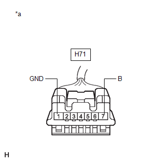
(a) Disconnect the steering lock ECU (steering lock actuator or upper bracket assembly) connector.
| (b) Measure the resistance according to the value(s) in the table below. Standard Resistance:
NOTICE: If the result is not as specified, check for looseness in the ground cable connection. |
|
(c) Measure the voltage according to the value(s) in the table below.
Standard Voltage:
| Tester Connection | Condition | Specified Condition |
|---|---|---|
| H71-7 (B) - Body ground | Always | 11 to 14 V |
| NG |
 | REPAIR OR REPLACE HARNESS OR CONNECTOR |
|

| 6. | CHECK STEERING LOCK ECU (STEERING LOCK ACTUATOR OR UPPER BRACKET ASSEMBLY) |
(a) Connect the steering lock ECU (steering lock actuator or upper bracket assembly) connector.
| (b) Measure the voltage according to the value(s) in the table below. Standard Voltage:
|
|
| OK |
 | REPLACE STEERING LOCK ECU (STEERING LOCK ACTUATOR OR UPPER BRACKET ASSEMBLY) |
|

| 7. | CHECK HARNESS AND CONNECTOR (STEERING LOCK ECU (STEERING LOCK ACTUATOR OR UPPER BRACKET ASSEMBLY) - CERTIFICATION ECU (SMART KEY ECU ASSEMBLY)) |
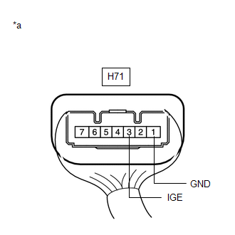
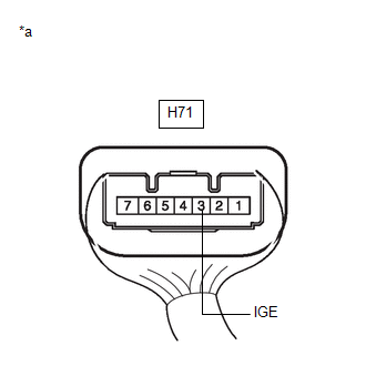
(a) Disconnect the H71 steering lock ECU (steering lock actuator or upper bracket assembly) connector.
(b) Disconnect the H46 certification ECU (smart key ECU assembly) connector.
(c) Measure the resistance according to the value(s) in the table below.
Standard Resistance:
| Tester Connection | Condition | Specified Condition |
|---|---|---|
| H71-3 (IGE) - H46-24 (SLR+) | Always | Below 1 Ω |
| H71-3 (IGE) or H46-24 (SLR+) - Other terminals and body ground | Always | 10 kΩ or higher |
| NG |
 | REPAIR OR REPLACE HARNESS OR CONNECTOR |
|

| 8. | CHECK STEERING LOCK ECU (STEERING LOCK ACTUATOR OR UPPER BRACKET ASSEMBLY) |
(a) Connect the steering lock ECU (steering lock actuator or upper bracket assembly) connector.
| (b) Measure the voltage according to the value(s) in the table below. Standard Voltage:
|
|
| OK |
 | REPLACE CERTIFICATION ECU (SMART KEY ECU ASSEMBLY) |
| NG |
 | REPLACE STEERING LOCK ECU (STEERING LOCK ACTUATOR OR UPPER BRACKET ASSEMBLY) |
| 9. | INSPECT CLUTCH START SWITCH ASSEMBLY |
Click here

| NG |
 | REPLACE CLUTCH START SWITCH ASSEMBLY |
|

| 10. | CHECK HARNESS AND CONNECTOR (CERTIFICATION ECU (SMART KEY ECU ASSEMBLY) - CLUTCH START SWITCH ASSEMBLY) |
(a) Disconnect the H45 certification ECU (smart key ECU assembly) connector.
(b) Disconnect the A64 clutch start switch assembly connector.
(c) Disconnect the A106 ECM connector.
(d) Disconnect the A67 engine stop and start ECU connector.
(e) Measure the resistance according to the value(s) in the table below.
Standard Resistance:
| Tester Connection | Condition | Specified Condition |
|---|---|---|
| H45-10 (STAR) - A106-23 (NSW) | Always | Below 1 Ω |
| H45-10 (STAR) - A64-2 (B) | Always | Below 1 Ω |
| H45-3 (STA) or A64-1 (L) - Other terminals and body ground | Always | 10 kΩ or higher |
| H45-10 (STAR) or A106-23 (NSW) - Other terminals and body ground | Always | 10 kΩ or higher |
| H45-10 (STAR) or A64-2 (B) - Other terminals and body ground | Always | 10 kΩ or higher |
| OK |
 | REPLACE CERTIFICATION ECU (SMART KEY ECU ASSEMBLY) |
| NG |
 | REPAIR OR REPLACE HARNESS OR CONNECTOR |
 New Key Registration Warning Message is not Displayed
DESCRIPTION If the new key registration warning message is not displayed after an electrical key transmitter sub-assembly has been registered, there may be communication problem between the certification ECU (smart key ECU assembly) and combination meter assembly (meter ECU)...
 Steering Lock does not Lock
DESCRIPTION The steering lock ECU (steering lock actuator or upper bracket assembly) activates the steering lock motor and moves the lock bar into the steering column to lock the steering...
Other information:
Toyota Yaris XP210 (2020-2026) Owner's Manual: Child-Restraint Precautions
Toyota strongly urges the use of child-restraint systems for children small enough to use them. You are required by law to use a child-restraint system for children in the U.S. and Canada. Check your local and state or provincial laws for specific requirements regarding the safety of children riding in your vehicle...
Toyota Yaris XP210 (2020-2026) Reapir and Service Manual: Brake Switch "A" Circuit Open (P057113)
DESCRIPTION The skid control ECU (brake actuator assembly) detects the brake operating conditions through a signal transmitted by the stop light switch. The skid control ECU incorporates a circuit to detect an open circuit. This DTC is output when an open circuit is detected in the stop light signal input line...
Categories
- Manuals Home
- Toyota Yaris Owners Manual
- Toyota Yaris Service Manual
- Maintenance
- Opening and Closing the Liftgate/Trunk Lid
- Immobilizer System
- New on site
- Most important about car
Liftgate/Trunk Lid
WARNING
Never allow a person to ride in the luggage compartment/trunk
Allowing a person to ride in the luggage compartment/trunk is dangerous. The person in the luggage compartment/trunk could be seriously injured or killed during sudden braking or a collision.
Do not drive with the liftgate/trunk lid open