Toyota Yaris: Front Radar Sensor System / System Diagram
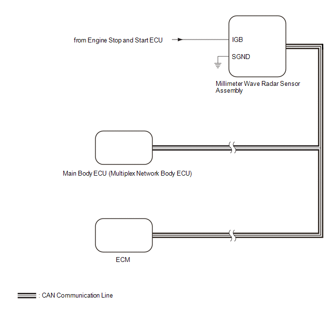
SYSTEM DIAGRAM
 Parts Location
P..
 How To Proceed With Troubleshooting
CAUTION / NOTICE / HINT HINT:
Before performing troubleshooting for the front radar sensor system, perform troubleshooting for the pre-collision system...
Other information:
Toyota Yaris XP210 (2020-2026) Reapir and Service Manual: A Camshaft Position Actuator Bank 1 Circuit Open (P001013)
DESCRIPTION The Variable Valve Timing (VVT) system adjusts the intake valve timing to improve driveability. The engine oil pressure turns the VVT controller to adjust the valve timing. The cam timing oil control solenoid assembly (for intake camshaft) operates according to signals received from the ECM to control the position of the camshaft timing oil control valve assembly and supply engine oil...
Toyota Yaris XP210 (2020-2026) Reapir and Service Manual: Components
COMPONENTS ILLUSTRATION *1 STEERING COLUMN HOLE COVER *2 STEERING LINK ASSEMBLY Tightening torque for "Major areas involving basic vehicle performance such as moving/turning/stopping": N*m (kgf*cm, ft.*lbf) - - ILLUSTRATION *1 TIE ROD END SUB-ASSEMBLY LH *2 TIE ROD END SUB-ASSEMBLY RH *3 STEERING LINK ASSEMBLY - - Tightening torque for "Major areas involving basic vehicle performance such as moving/turning/stopping": N*m (kgf*cm, ft...
Categories
- Manuals Home
- Toyota Yaris Owners Manual
- Toyota Yaris Service Manual
- To Set Speed
- Engine & Hybrid System
- Diagnostic Trouble Code Chart
- New on site
- Most important about car
Break-In Period
No special break-in is necessary, but a few precautions in the first 600 miles (1,000 km) may add to the performance, economy, and life of the vehicle.
Do not race the engine. Do not maintain one constant speed, either slow or fast, for a long period of time. Do not drive constantly at full-throttle or high engine rpm for extended periods of time. Avoid unnecessary hard stops. Avoid full-throttle starts.
Copyright © 2026 www.toyaris4.com