Toyota Yaris: Front Camera System / System Diagram
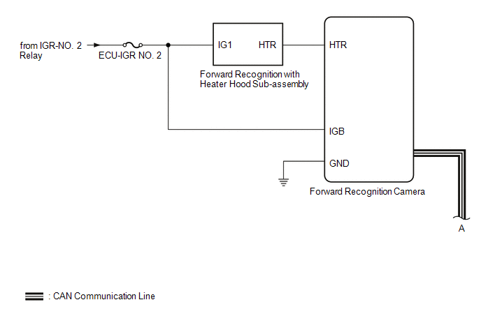
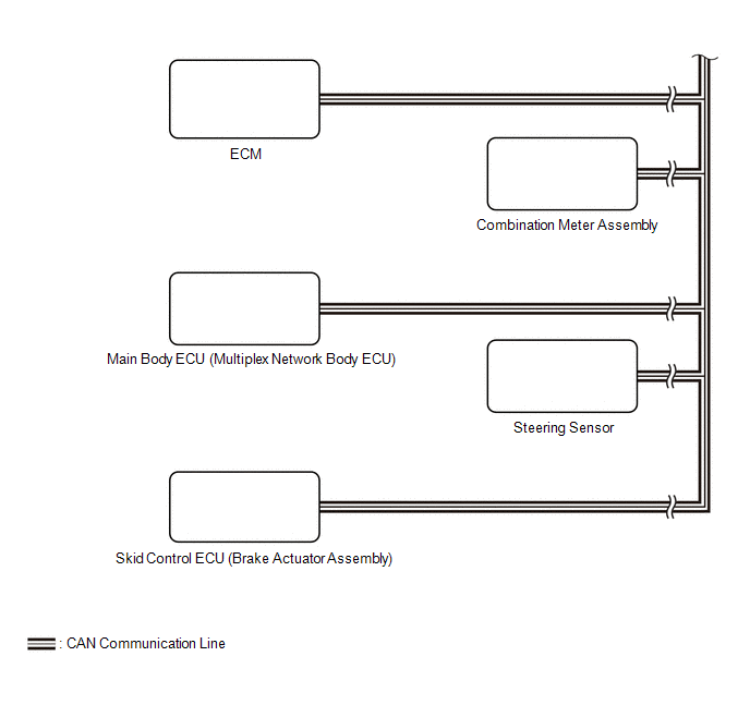
SYSTEM DIAGRAM
 Parts Location
PARTS LOCATION ILLUSTRATION
*1 FORWARD RECOGNITION CAMERA *2 FORWARD RECOGNITION WITH HEATER HOOD SUB-ASSEMBLY *3 BRAKE ACTUATOR ASSEMBLY - SKID CONTROL ECU *4 ECM ILLUSTRATION
*1 COMBINATION METER ASSEMBLY *2 STEERING SENSOR *3 MAIN BODY ECU (MULTIPLEX NETWORK BODY ECU) *4 POWER DISTRIBUTION BOX ASSEMBLY - ECU-IGR NO...
 How To Proceed With Troubleshooting
CAUTION / NOTICE / HINT HINT:
Before performing troubleshooting for the front camera system, perform troubleshooting for the pre-collision system.
Click here
If a pre-collision system related warning message is displayed on the multi-information display, refer to How to Proceed with Troubleshooting for Pre-collision System...
Other information:
Toyota Yaris XP210 (2020-2026) Reapir and Service Manual: Vehicle Control History
VEHICLE CONTROL HISTORY DESCRIPTION Vehicle Control History is a function that captures and stores ECU data when triggered by specific vehicle behavior. It may be possible to determine the cause of the malfunction by checking the vehicle history information and freeze frame data...
Toyota Yaris XP210 (2020-2026) Reapir and Service Manual: Inspection
INSPECTION PROCEDURE 1. INSPECT OCCUPANT DETECTION SENSOR (SEPARATE TYPE FRONT SEAT CUSHION PAD) (a) Check the resistance. (1) Measure the resistance according to the value(s) in the table below. Standard Resistance: Tester Connection Condition Specified Condition If the result is not as specified, replace the occupant detection sensor (separate type front seat cushion pad)...
Categories
- Manuals Home
- Toyota Yaris Owners Manual
- Toyota Yaris Service Manual
- Opening and Closing the Liftgate/Trunk Lid
- Immobilizer System
- Fuel Gauge
- New on site
- Most important about car
Fuel-Filler Lid and Cap
WARNING
When removing the fuel-filler cap, loosen the cap slightly and wait for any hissing to stop, then remove it
Fuel spray is dangerous. Fuel can burn skin and eyes and cause illness if ingested. Fuel spray is released when there is pressure in the fuel tank and the fuel-filler cap is removed too quickly.
Copyright © 2026 www.toyaris4.com