Toyota Yaris: Active Torque Split Awd System / System Diagram
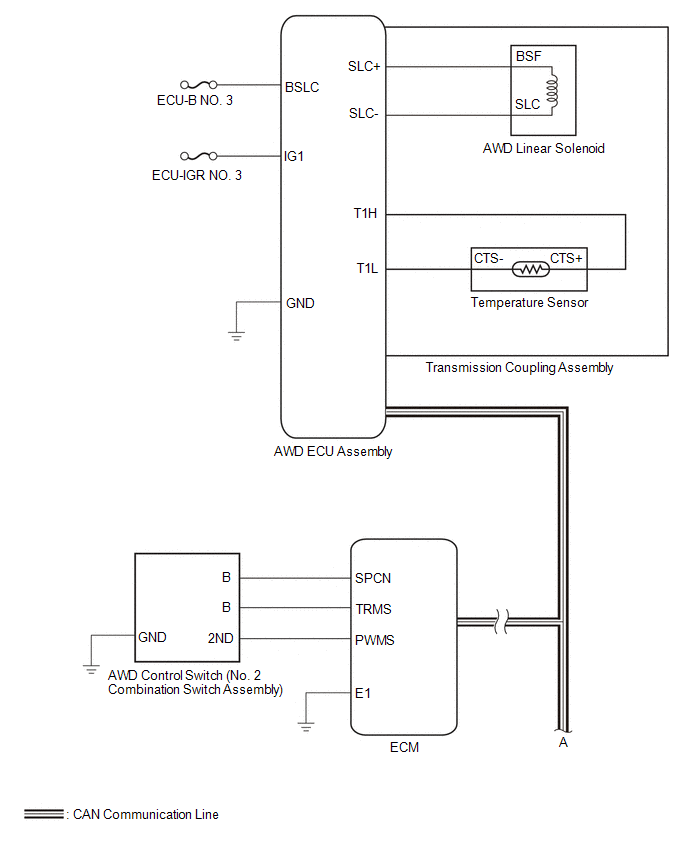
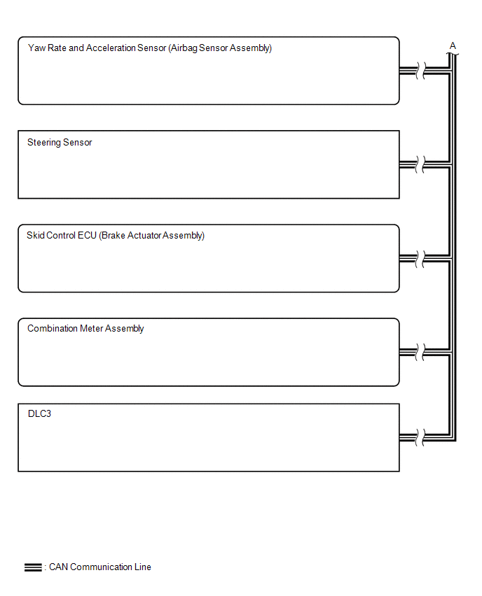
Toyota Yaris XP210 (2020-2026) Reapir and Service Manual / Drivetrain / Gf1a (transfer / 4wd / Awd) / Active Torque Split Awd System / System Diagram

SYSTEM DIAGRAM

    Parts Location

    PARTS LOCATION ILLUSTRATION *1 BRAKE ACTUATOR ASSEMBLY - SKID CONTROL ECU *2 ECM *3 TEMPERATURE SENSOR *4 AWD LINEAR SOLENOID (TRANSMISSION COUPLING ASSEMBLY) *5 AWD ECU ASSEMBLY - - ILLUSTRATION *1 COMBINATION METER ASSEMBLY - AWD WARNING (MULTI-INFORMATION DISPLAY) *2 AWD CONTROL SWITCH (NO...

    How To Proceed With Troubleshooting

    CAUTION / NOTICE / HINT HINT: Use the following procedure listed to troubleshoot the Active Torque Split AWD System. *: Use the GTS. PROCEDURE 1...

    Other information:

    Toyota Yaris XP210 (2020-2026) Reapir and Service Manual: Terminals Of Ecu


    TERMINALS OF ECU CHECK STEREO COMPONENT EQUALIZER ASSEMBLY Terminal No. (Symbol) Terminal Description Condition Specified Condition O131-15(+B) - O131-30(GND) Power source Always 11 to 14 V O131-29(IGP) - O131-30(GND) Power source (IG) Ignition switch ON 11 to 14 V O131-14(ACC) - O131-30(GND) Power source (ACC) Ignition switch ACC 11 to 14 V O131-30(GND) - Body ground Ground Always Below 1 Ω O132-1(MC1+) - O131-30(GND) Active noise control microphone input signal Active noise control microphone LH tapped with finger Pulse generation O132-5(MC1-) - O131-30(GND) Active noise control microphone input signal Always Below 1 Ω O132-2(MC2+) - O131-30(GND) Active noise control microphone input signal Active noise control microphone RH tapped with finger Pulse generation O132-6(MC2-) - O131-30(GND) Active noise control microphone input signal Always Below 1 Ω O131-3(NEI) - O131-30(GND) Engine pulse signal Idling with warm engine Pulse generation (See waveform 1) O131-24(FLI-) Active noise control microphone output signal - - O131-9(FLI+) Active noise control microphone output signal - - O131-23(FRI-) Active noise control microphone output signal - - O131-8(FRI+) Active noise control microphone output signal - - O131-5(RRI+) Active noise control microphone output signal - - O131-20(RRI-) Active noise control microphone output signal - - O131-6(RLI+) Active noise control microphone output signal - - O131-21(RLI-) Active noise control microphone output signal - - O131-7(ASG1) Shield ground - - O131-22(ASG2) Shield ground - - O131-12(FR+) - O131-30(GND) Sound signal Active noise control system operating Pulse generation O131-27(FR-) - O131-30(GND) Sound signal Active noise control system operating Pulse generation O131-13(FL+) - O131-30(GND) Sound signal Active noise control system operating Pulse generation O131-28(FL-) - O131-30(GND) Sound signal Active noise control system operating Pulse generation O131-10(RR+) - O131-30(GND) Sound signal Active noise control system operating Pulse generation O131+25(RR-) - O131-30(GND) Sound signal Active noise control system operating Pulse generation O131-11(RL+) - O131-30(GND) Sound signal Active noise control system operating Pulse generation O131-28(RL-) - O131-30(GND) Sound signal Active noise control system operating Pulse generation O131-1(CANH) CAN communication signal - - O131-16(CANL) CAN communication signal - - (a) Waveform 1 HINT: The oscilloscope waveform shown in the illustration is an example for reference only...

    Toyota Yaris XP210 (2020-2026) Reapir and Service Manual: Inspection


    INSPECTION PROCEDURE 1. INSPECT STEERING WHEEL SWITCH HOUSING (a) Check the resistance. (1) Measure the resistance according to the value(s) in the table below. *a Component without harness connected (Steering Wheel Switch Housing) - - Standard Resistance: Light Switch Circuit Tester Connection Condition Specified Condition z6-3 (T) - z4-3 (T) Always Below 1 Ω z6-12 (H) - z4-4 (H) Always Below 1 Ω z6-7 (A) - z4-5 (A) Always Below 1 Ω z6-16 (HU) - z4-6 (HU) Always Below 1 Ω z6-11 (HF) - z4-7 (HF) Always Below 1 Ω z6-8 (TR) - z4-8 (TR) Always Below 1 Ω z6-14 (TL) - z4-9 (TL) Always Below 1 Ω z6-6 (CR) - z4-10 (CR) Always Below 1 Ω z6-13 (BFG) - z4-11 (BFG) Always Below 1 Ω z6-4 (B) - z4-12 (B) Always Below 1 Ω z6-5 (EL) - z4-13 (EL) Always Below 1 Ω Wiper Switch Circuit Tester Connection Condition Specified Condition z5-10 (W_OFF) - z4-24 (W_OFF) Always Below 1 Ω z5-13 (+S) - z4-25 (+S) Always Below 1 Ω z5-11 (+1) - z4-26 (+1) Always Below 1 Ω z5-12 (+2) - z4-27 (+2) Always Below 1 Ω z5-14 (MIST) - z4-28 (MIST) Always Below 1 Ω z5-15 (WF) - z4-31 (WF) Always Below 1 Ω z5-5 (E) - z4-33 (E) Always Below 1 Ω z5-4 (VR) - z4-34 (VR) Always Below 1 Ω If the result is not as specified, replace the steering wheel switch housing...

    Categories

    Key Suspend Function

    If a key is left in the vehicle, the functions of the key left in the vehicle are temporarily suspended to prevent theft of the vehicle.

    To restore the functions, press the unlock button on the functions-suspended key in the vehicle.

    read more

     
    Copyright © 2026 www.toyaris4.com