Toyota Yaris: Vehicle Stability Control System / System Diagram
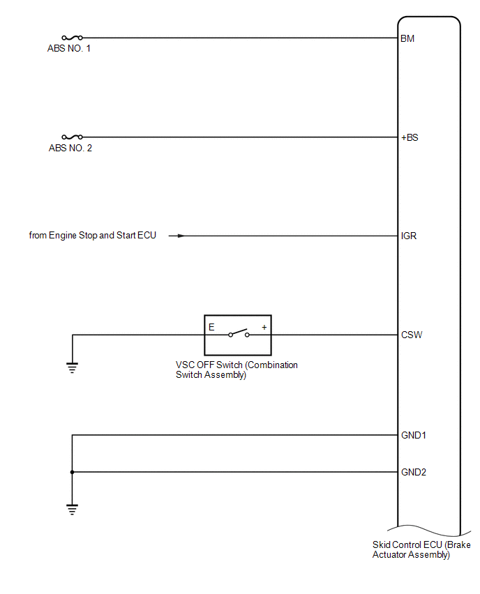
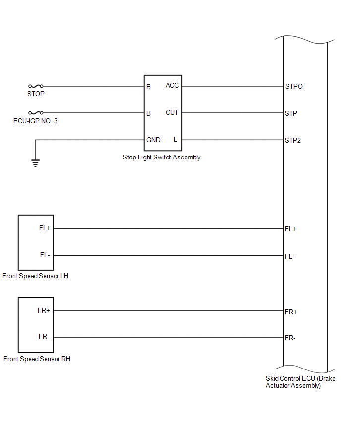
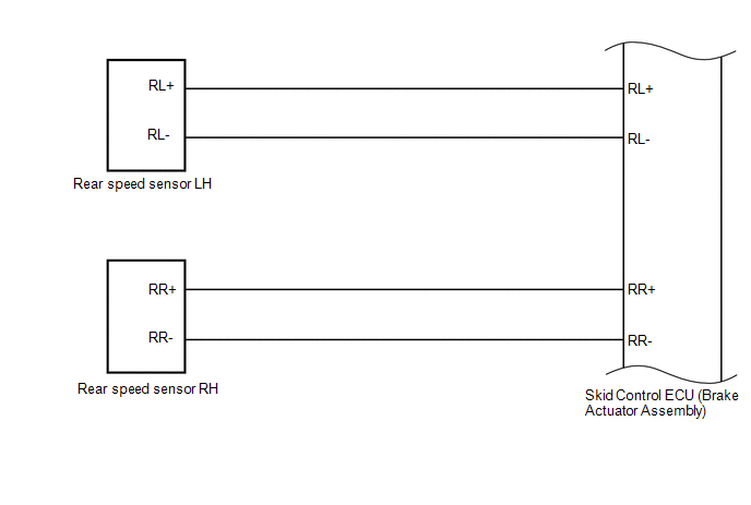
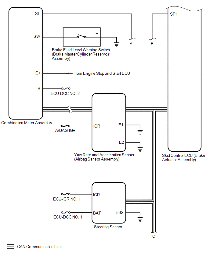
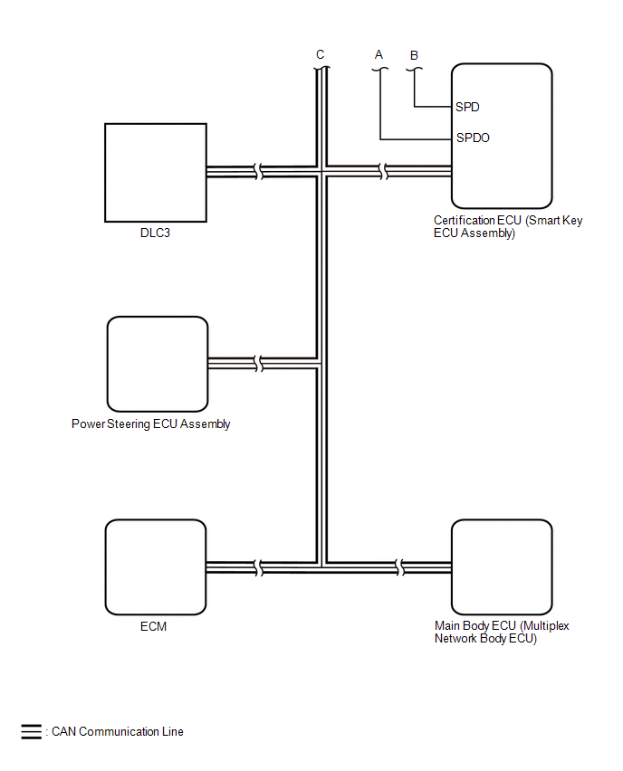
SYSTEM DIAGRAM
 Parts Location
PARTS LOCATION ILLUSTRATION
*1 FRONT AXLE HUB SUB-ASSEMBLY RH - FRONT SPEED SENSOR ROTOR RH *2 FRONT SPEED SENSOR RH *3 REAR AXLE HUB AND BEARING ASSEMBLY RH - REAR SPEED SENSOR ROTOR RH *4 REAR SPEED SENSOR RH *5 REAR AXLE HUB AND BEARING ASSEMBLY LH - REAR SPEED SENSOR ROTOR LH *6 REAR SPEED SENSOR LH *7 FRONT AXLE HUB SUB-ASSEMBLY LH - FRONT SPEED SENSOR ROTOR LH *8 FRONT SPEED SENSOR LH ILLUSTRATION
*1 ECM *2 NO...
 How To Proceed With Troubleshooting
CAUTION / NOTICE / HINT HINT: *: Use the GTS. PROCEDURE 1. VEHICLE BROUGHT TO WORKSHOP
NEXT
2. CUSTOMER PROBLEM ANALYSIS (a) Interview the customer and confirm the problem...
Other information:
Toyota Yaris XP210 (2020-2026) Owner's Manual: Exterior Care
The paintwork on your Toyota represents the latest technical developments in composition and methods of application. Environmental hazards, however, can harm the paint’s protective properties, if proper care is not taken. Here are some examples of possible damage, with tips on how to prevent them...
Toyota Yaris XP210 (2020-2026) Reapir and Service Manual: Removal
REMOVAL CAUTION / NOTICE / HINT NOTICE: Make sure to use Toyota Genuine Windshield Glass Adhesive (High Modulus Type) or equivalent. HINT: Use the same procedure for the RH side and LH side. The following procedure is for the LH side. PROCEDURE 1...
Categories
- Manuals Home
- Toyota Yaris Owners Manual
- Toyota Yaris Service Manual
- Power Integration No.1 System Missing Message (B235287,B235587,B235787-B235987)
- Maintenance
- G16e-gts (engine Mechanical)
- New on site
- Most important about car
Supplemental Restraint System (SRS) Precautions
The front and side supplemental restraint systems (SRS) include different types of air bags. Please verify the different types of air bags which are equipped on your vehicle by locating the “SRS AIRBAG” location indicators. These indicators are visible in the area where the air bags are installed.
The air bags are installed in the following locations:
The steering wheel hub (driver air bag) The front passenger dashboard (front passenger air bag) The outboard sides of the front seatbacks (side air bags) The front and rear window pillars, and the roof edge along both sides (curtain air bags)
Copyright © 2026 www.toyaris4.com