Toyota Yaris: Smart Key System (for Start Function) / System Diagram
SYSTEM DIAGRAM
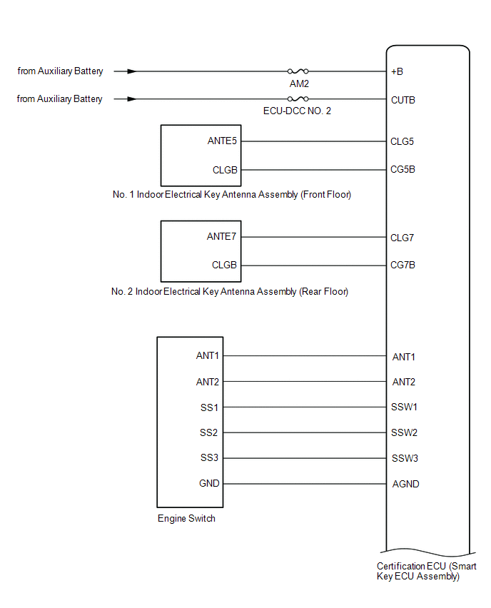
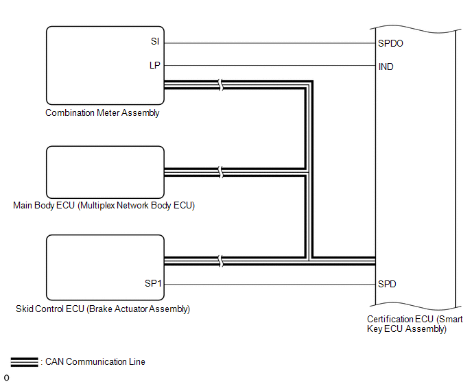
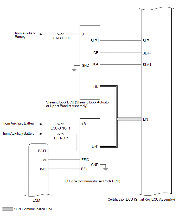
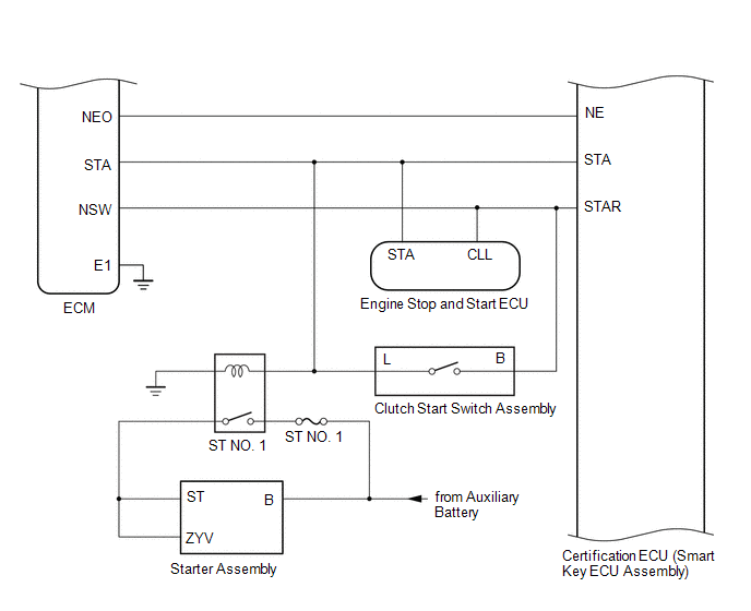
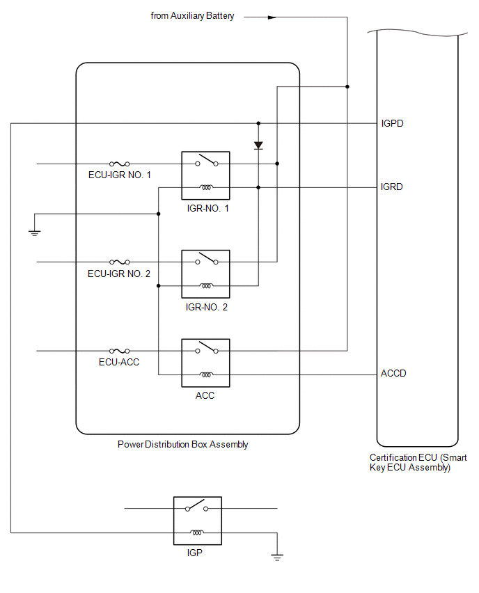
SMART KEY SYSTEM (for Start Function)
SMART KEY SYSTEM (for Entry Function)
Click here

 Parts Location
PARTS LOCATION ILLUSTRATION
*1 ECM *2 NO. 1 ENGINE ROOM RELAY BLOCK ASSEMBLY - ST NO. 1 FUSE - EFI NO. 1 FUSE - IGP RELAY - ST NO. 1 RELAY *3 SKID CONTROL ECU (BRAKE ACTUATOR ASSEMBLY) - - ILLUSTRATION
*1 NO...
 How To Proceed With Troubleshooting
CAUTION / NOTICE / HINT HINT:
Replace parts related to the wireless door lock control system and smart key system according to the inspection procedure...
Other information:
Toyota Yaris XP210 (2020-2026) Reapir and Service Manual: Backup Boost Converter Circuit Board(Thermistor) Signal Compare Failure (P30DF62,P30EF4B,P323A00,P323A16,P323AA2,P323B29,P323B38)
DESCRIPTION Refer to DTC P323A19. Click here DTC No. Detection Item DTC Detection Condition Trouble Area Warning Indicate Memory Note P30DF62 Backup Boost Converter Circuit Board(Thermistor) Signal Compare Failure The following conditions is met for 1 second or more (1 trip detection logic): Difference in temperature between thermistor 1 and thermistor 2 of the engine stop and start ECU is 40°C (72°F) or higher...
Toyota Yaris XP210 (2020-2026) Reapir and Service Manual: Cruise Control Input Processor (P160700)
DESCRIPTION When the ECM detects that it is not functioning normally, DTC P160700 is stored. DTC No. Detection Item DTC Detection Condition Trouble Area DTC Output from P160700 Cruise Control Input Processor When the ignition switch is ON and control of vehicle speed by the dynamic radar cruise control system is prohibited by the sub-CPU, the dynamic radar cruise control system operates for 0...
Categories
- Manuals Home
- Toyota Yaris Owners Manual
- Toyota Yaris Service Manual
- Engine Start Function When Key Battery is Dead
- Diagnostic Trouble Code Chart
- Removal
- New on site
- Most important about car
Refueling
Before refueling, close all the doors, windows, and the liftgate/trunk lid, and switch the ignition OFF.
To open the fuel-filler lid, pull the remote fuel-filler lid release.

Copyright © 2026 www.toyaris4.com