Toyota Yaris: Ignition System / System Diagram
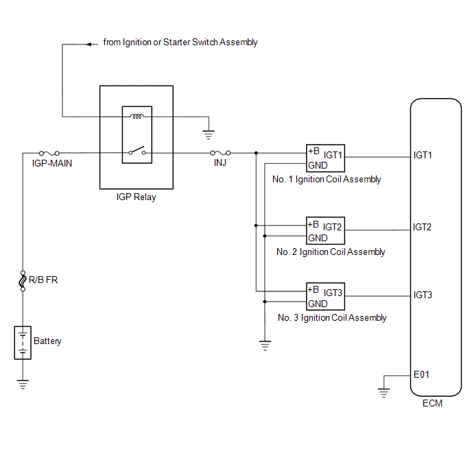
SYSTEM DIAGRAM
 Parts Location
P..
 On-vehicle Inspection
ON-VEHICLE INSPECTION CAUTION / NOTICE / HINT CAUTION: To prevent injury due to contact with an operating V-ribbed belt or cooling fan, keep your hands and clothing away from the V-ribbed belt and cooling fan when working in the engine compartment with the engine running or the ignition switch on (IG)...
Other information:
Toyota Yaris XP210 (2020-2026) Reapir and Service Manual: Installation
INSTALLATION CAUTION / NOTICE / HINT HINT: Use the same procedure for the RH side and LH side. The following procedure is for the LH side. PROCEDURE 1. INSTALL CURTAIN SHIELD AIRBAG ASSEMBLY NOTICE: When installing a curtain shield airbag assembly, have assistants hold it to prevent it from bending...
Toyota Yaris XP210 (2020-2026) Reapir and Service Manual: Calibration
CALIBRATION DESCRIPTION (a) Refer to the table below and then perform the necessary operation according to the part to be replaced in order to perform calibration. Parts to be Replaced / Operation Necessary Operation Skid control ECU (brake actuator assembly) Calibration Yaw rate and acceleration sensor (airbag sensor assembly) Calibration Wheel alignment adjustment Calibration UTILITY ITEMS Utility Items Main Purpose Link All Readiness Confirm if DTC judgment has been completed...
Categories
- Manuals Home
- Toyota Yaris Owners Manual
- Toyota Yaris Service Manual
- Key Battery Replacement
- How to connect USB port/Auxiliary jack
- Adjustment
- New on site
- Most important about car
Key Suspend Function
If a key is left in the vehicle, the functions of the key left in the vehicle are temporarily suspended to prevent theft of the vehicle.
To restore the functions, press the unlock button on the functions-suspended key in the vehicle.
Copyright © 2026 www.toyaris4.com